28
24 - ACCESSORIES AND SENSORS
EXTERNAL ENTRAPMENT PROTECTION
Non-contact and contact sensors must be installed individually or in combination with each other to provide external entrapment protection.
Care should be exercised to reduce the risk of nuisance tripping, such as when a vehicle trips the sensor while the gate is still moving, and one or more non-
contact sensors shall be located where the risk of entrapment or obstruction exists, such as the perimeter reachable by a moving gate or barrier.
A hardwired contact sensor shall be located and its wiring arranged so that the communication between the sensor and the gate operator is not subjected to
mechanical damage.
A wireless contact sensor such as one that transmits radio frequency (RF) signals to the gate operator for entrapment protection functions shall be located
where the transmission of the signals are not obstructed or impeded by building structures, natural landscaping or similar obstruction. See the 1551 manual
for more information on external entrapment sensors and installation instructions.
DURING INSTALLATION
• DISCONNECT POWER at the control panel before making any electric service power connection.
• Be aware of all moving parts and avoid close proximity to any pinch points.
• Know how to operate the manual release.
• Adjust the unit to use the minimum force required to operate the gate smoothly even during mid-travel reversing.
• Place controls a minimum of 8 feet away from the gate so that the user can see the gate and operate controls but cannot touch the gate or gate operator
while operating the controls.
• Warning signs must be placed on each side of the gate or in high-visibility areas to alert of automatic gate operations.
25.1 - Monitored Safety Device
BlueBus photo-eyes:
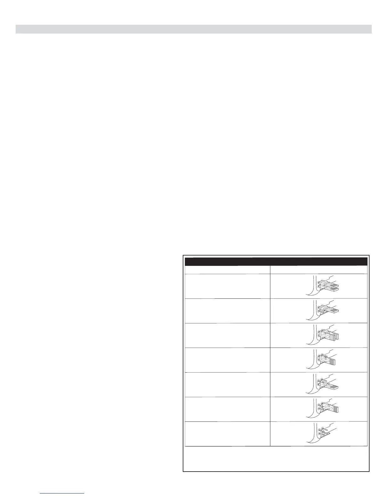
The EPMOB photocell is a thru-beam device - consisting of a transmitter (TX) and a receiver (RX) that connects via two (2) wires. Polarity of the wiring is
not important. EPMOBs may be wired in parallel to one another or directly to the board - it is not necessary to make a “home run” to the board with each
EPMOB. Multiple sets of EPMOBs may be used, however each PAIR must be set to an exclusive address by setting the jumpers in the units. What this
means, is that each pair of eyes must have their jumpers set to match each other - but every pair must be set differently from the other pairs. The address
jumpers also determine the functionality of each set of eyes:Open direction or Close direction, etc. (see Table 1).
1. Mount the transmitter and receiver appropriately to a rigid mounting surface. Eyes should be placed appropriately to protect areas of entrapment
according to UL325 guidelines.
2. Set the jumpers in each pair of eyes to match each other.
Ensure that each pair of eyes are set differently. Use the table
below to nd the setting of the jumpers that corresponds to
the functionality desired from each pair of eyes.
3. Connect the EPMOBs to the Bluebus connector of the circuit
board. Polarity of the wiring is not important. Eyes may be
connected in parallel to one another - or directly to the board.
4. LEARN the Bluebus port.
On a 1050 board - Press Functions (1. Learn) - Press “OK”
(Learn Bluebus) - Press “OK”. Allow the board to scan the
Bluebus Port.
When complete - test the functionality of each set of eyes.
5. Fine tune the alignment of each pair of eyes. The more slowly
the lights ash on the units - the better they are aligned.
Close Direction A/B: Resets timer to close in open position, reverses
gate if closing, no effect if gate is closed or during opening cycling. Typi-
cally used when the photo eyes are on the outside of the property (gates
opening inward.
Close Direction 2 A/B: Resets timer to close in open position, revers-
es gate if closing AFTER obstruction is cleared, pauses the gate on
opening cycle - opening resumes after obstruction clears. Typically used
when the photo eyes are on the inside of the property (gates opening
inward).
Open Direction A/B: Delays gate opening from closed position. Stops
and reverses gate back closed on open cycle. Typically used to protect an
entrapment point when the gates are opening.
Photocell
CLOSE DIRECTION A
Jumpers
Table 1
CLOSE DIRECTION B
CLOSE DIRECTION 2A
CLOSE DIRECTION 2B
OPEN DIRECTION A
OPEN DIRECTION B
NOT USED