29
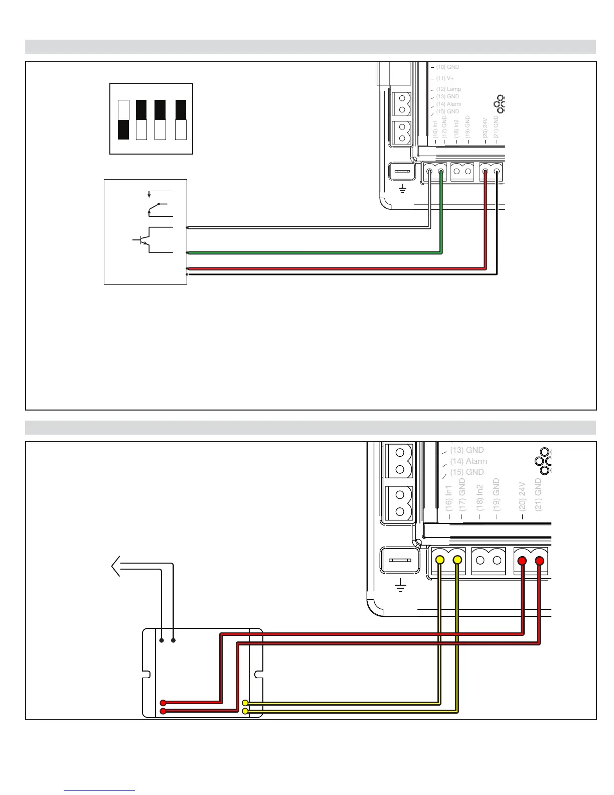
25 - IRB-RET Wiring Diagram
26 - GEM-103 Wiring Diagram
1. Press “Functions”
2. Select #3 “Auxiliary IO” and Press “OK”
3. Select “In Aux 1” (or “In Aux 2”) and Press “OK”.
4. Select “Pulse Open” or “Pulse Close” and “Press OK”
5. Connect 300Hz Monitored Safety Device to In1 (16) or In2 (18) accordingly.
NOTES:
*Only one monitored (Pulse) device may be connected per programmable input: In1 or In2.
*At least one monitored device must be properly connected to 1050 boards that are UL325 7th Edition in order to
complete the “Learn” mode. A “BlueBus Error” will result if this requirement is not met.
ON
2 FREQUENCY
IRB-RET
NO
NC
C
E
VRX
COM
1 2 3 4
B W
GEM-103
TO 10K OHM RESISTANCE
EDGE SENSOR
Black & White
Wires