English – 11
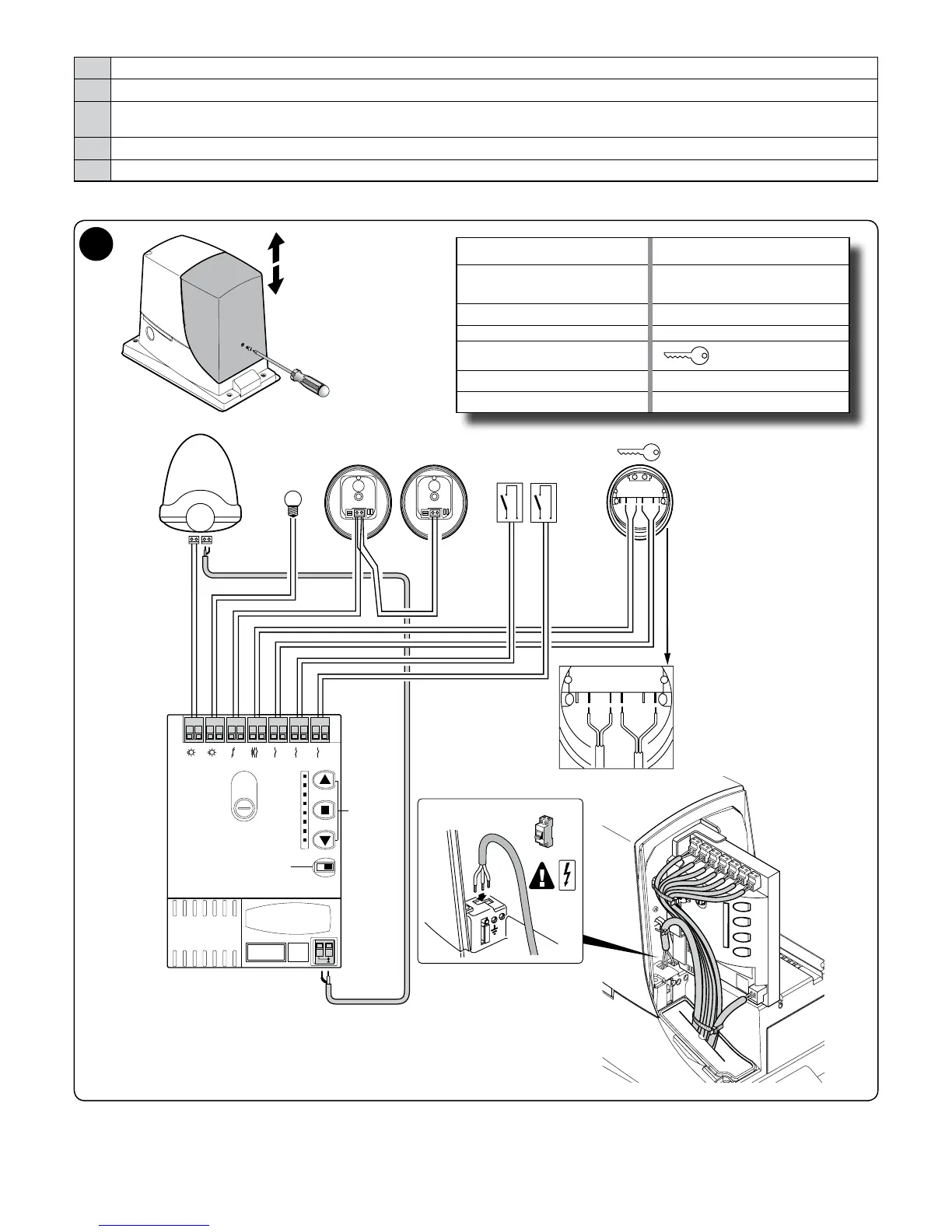
To make the electrical connections, proceed as described below and refer to Fig. 7:
01. Open the cover: loosen the screw and raise the cover
02. Feed the power cable through the relevant hole (leave 20/30 cm of free cable) and connect it to the relevant terminal clamp
03. Feed the cables of the devices to be installed or already present in the system through the relevant hole (leave 20/30 cm of free cable)
and connect them to their terminal clamps as shown in Fig. 7
04. Before closing the cover, program the system: Chapter 7
05. Close the cover with the relevant screw
7
SELECTOR =
DIRECTION
SELECTOR
S.C.A. =
G.O.I. (Gate Open
Indicator)
KEYS =
PROGRAMMING
AND CONTROL
KEYS
TX - RX = PHOTOCELLS
LED = FUNCTION LEDS OPEN = OPEN
RECEIVER = RADIO RECEIVER CLOSE = CLOSED
AERIAL = AERIAL
= KEY SELECTOR
FUSE = FUSE
FLASH = FLASHING LIGHT
L1
L2
L3
L4
L5
L6
L7
L8
Fuse 1.6 A
Receiver
TX
24V 4W
S.C.AFLASH
CLOSE
OPEN
RX
NC NO CC NO NC
KEYS
SELECTOR
LED
AERIAL
Flash
SCA
Bluebus
Stop
PP
Open
Close
OFF