26 – English
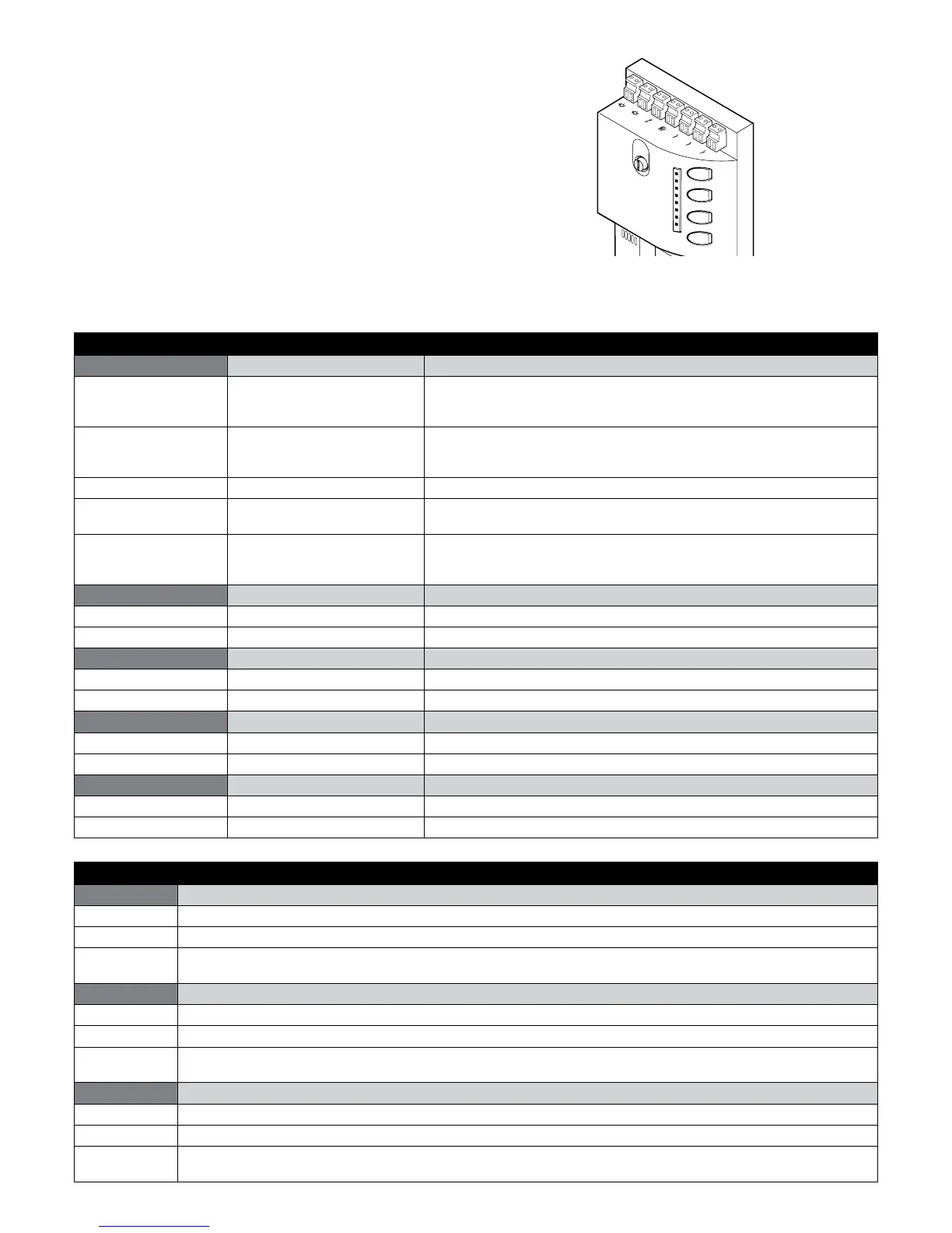
9.2.2 - Control unit signals
The ROBUS unit has a series of LEDs, each of which can emit special
signals both during regular operation and when a fault occurs.
Flash
SCA
Bluebus
Stop
PP
Open
Close
L1
L2
L3
L4
L5
L6
L7
L8
Table 19 - LED’s on the control unit’s terminals
BLUEBUS LED Cause Action
Off Fault Make sure there is power supply; check to see if the fuses are blown; if nec-
essary, identify the reason for the failure then replace them with others of the
same type
On Serious fault There is a serious fault; try switching off the control unit for a few seconds; if
the condition persists, it means there is a malfunction and the circuit board
has to be replaced
1 ash per second All OK Control unit works correctly
2 quick ashes Input status variation This is normal when there is a change in one of the inputs: OPEN, STOP, trig-
gering of photocells or the radio transmitter is used
Series of ashes sepa-
rated by a one-second
pause
Various This is the same signal that appears on the ashing light. See Table 18
STOP LED Cause Action
Off Intervention of the STOP input Check the devices connected to the STOP input
On All OK STOP input active
S.S. LED Cause Action
Off All OK S.S. input not active
On Intervention of the S.S. input Normal if the device connected to the S.S. input is active
OPEN LED Cause Action
Off All OK OPEN input not active
On Intervention of the OPEN input Normal if the device connected to the OPEN input is active
CLOSE LED Cause Action
Off All OK CLOSE input not active
On Intervention of the CLOSE input Normal if the device connected to the CLOSE input is active
Table 20 - LED’s on the control unit keys
L1 LED Description
Off During normal operation it signals that the “Automatic closing” mode is not active
On During normal operation it signals that the “Automatic closing” mode is active
Flashes • Function programming in progress
• If it ashes together with L2, it means that the device recognition phase must be carried out (Paragraph 7.6)
L2 LED Description
Off During normal operation it signals that the “Close after photo” mode is not active
On During normal operation it signals that the “Close after photo” mode is active
Flashes • Function programming in progress
• If it ashes together with L1, it means that the device recognition phase must be carried out (Paragraph 7.6)
L3 LED Description
Off During normal operation it signals that the “Always close” mode is not active
On During normal operation it signals that the “Always close” mode is active
Flashes • Function programming in progress
• If it ashes together with LED L4, the gate leaf length recognition phase must be carried out (Paragraph 7.7)