10 – English
6
4
ELECTRICAL CONNECTIONS
CAUTION! – All electrical connections must be made with the system disconnected from the power supply. Incorrect connec-
tions can cause damage to the equipment and injury to people.
CAUTION! – The cables used must be suited to the type of installation; for example a type-H03VV-F cable is recommended for
indoor environments, and a type-H07RN-F cable for outdoor environments.
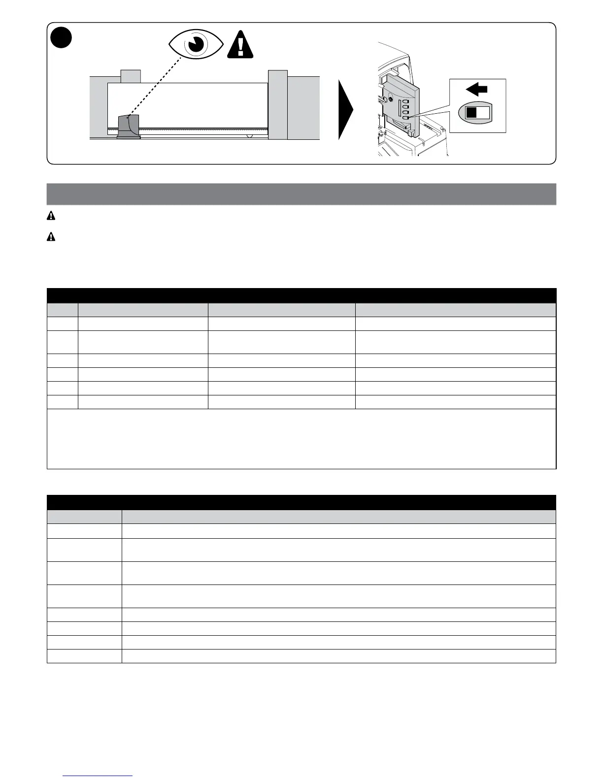
Fig. 2 shows the electrical connections in a typical installation; Fig. 7 shows the connections to be made on the control unit.
4.1 - Types of electrical cables
Table 3 - Types of electrical cable (see Fig. 2)
Connection Type of cable Maximum length
A POWER SUPPLY 1 cable: 3 x 1.5 mm
2
30 m *
B FLASHING LIGHT WITH AERIAL 1 cable: 2 x 0.5 mm
2
1 type-RG58 shielded cable
20 m
20 m (recommended < 5 m)
C PHOTOCELLS 1 cable: 2 x 0.25 mm
2
30 m **
D KEY SELECTOR 2 cables: 2 x 0.5 mm
2
*** 50 m
E FIXED EDGES 1 cable: 2 x 0.5 mm
2
**** 30 m
F MOVABLE EDGES 1 cable: 2 x 0.5 mm
2
**** 30 m *****
*
**
***
****
*****
If the power supply cable is longer than 30 m, a cable with larger gauge is required, e.g. 3 x 2.5 mm
2
, and a safety earthing system
must be arranged near the automation.
If the “BLUEBUS” cable is longer than 30 m, up to maximum 50 m, a 2 x 1 mm
2
cable is required.
The two 2 x 0.5 mm
2
cables can be replaced by a single 4 x 0.5 mm
2
cable.
If more than one edge is present, refer to Paragraph 8.1 “STOP Input” for the type of connection recommended.
Special devices, which enable connection even when the leaf is moving, must be used to connect movable edges to sliding leaves.
4.2 - Electrical cable connections: Fig. 7
Table 4 - Description of electrical connections
Function Description
FLASH - output for one or two “LUCYB” or similar type ashing lights with 12 V bulb only, maximum 21 W
S.C.A. - “Gate Open Indicator” output; a 24 V (max. 4 W) signal light can be connected. It can also be programmed for other
functions; refer to Paragraph 7.4 “Level 2 functions”
BLUEBUS - this terminal allows for connecting compatible devices; all are connected in parallel with just two wires conveying both
the power and the communication signals. Further information on the BLUEBUS appears in Paragraph 8.1 “BLUEBUS”
STOP - input for the devices that block or even stop the current manoeuvre; contacts like “Normally Closed”, “Normally Open”
or constant resistance devices can be connected through special arrangements on the input
P. P. - input for devices that control movement in Step-Step mode; it is possible to connect “Normally Open” contacts
OPEN - input for devices that control the opening movement only; it is possible to connect “Normally Open” contacts
CLOSE - input for devices that control the closing movement only; it is possible to connect “Normally Open” contacts
AERIAL - input for connecting the aerial for the radio receiver (the aerial is incorporated on LUCY B)