AD3000 4 – PROFIBUS DP
NIDEC ASI S.P.A. – AD3000 COMMUNICATION MANUAL
IMAD30007EN 17
4.4 Connections
The PROFIBUS DP connector, located on the BASIS control board and identified with code J2 is a sub D 9-pin female connector; the pin
configuration can be seen in Table 4.5.
Pow er supply v oltage (+5V)
Receiv e/Transmit data – positiv e (B)
Receiv e/Transmit data – negativ e (A)
0V (reference potential for VP)
Table 4.5 - PROFIBUS DP connector signals
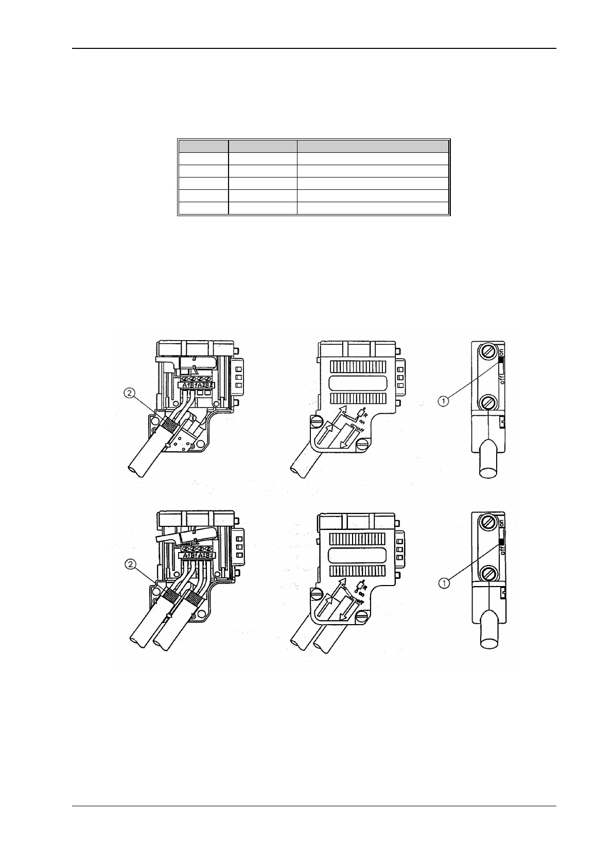
Figure 4.1 represents the PROFIBUS DP network connector, highlighting the switch for the insertion of the termination resistance in the last slave line.
Special care shall be put in ensuring shield continuity, which can be achieved by laying the bare cable braiding on the metal connector (ref. 2 of the
figure); moreover, the slave connection cable shall always be connected to the left, following the colour sequence for the connection to the screw
terminal board inside the connector.
Figure 4.1 - PROFIBUS DP connector