4 – PROFIBUS DP AD3000
NIDEC ASI S.P.A. – AD3000 COMMUNICATION MANUAL
18 IMAD30007EN
4.5 LED
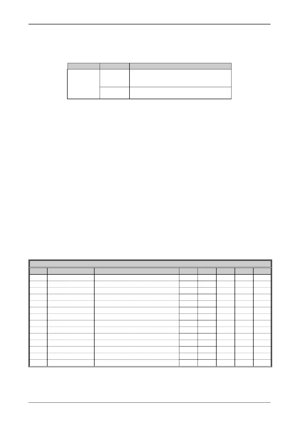
The communication status is indicated by LED DL1 on the ETH-PROFI board, see Table 4.6.
Normal communication betw een Master and AD3000. The
PROFIBUS DP interface is ex changing data w ith the
Master.
Communication not w orking betw een Master and AD3000. No
data ex change underw ay .
Table 4.6 - LED meaning
4.6 Protocol
The AD3000 is presented to the PROFIBUS DP network as a slave, enabled for data exchange functions. Data exchange is implemented according
to the PROFIdrive communication profile.
The protocol used is PROFIBUS DP-DP; with this standard, the message exchanged between master and slave can have five structure types,
identified with the following codes: PPO1, PPO2, PPO3, PPO4 and PPO5.
The above-mentioned codes univocally define , for the messages received and sent from the Drive protocol, both the message size (number of words)
and the position and typology of all the data in the message.
The types of data present in the messages are divided into two categories:
parameterisation data (PKW);
process data (PZD).
The drive control is able to manage both PKW parameterisation data and PZD process data.
4.7 Structure of messages sent and received through the PROFIBUS DP network
The following tables report the structure of every message received or sent by the AD3000 control according to the PPO used, the typology and
meaning of every word:
STRUCTURE OF RECEIVED MESSAGE
PKW - Parameterisation data
PKW - Parameterisation data
PKW - Parameterisation data
PKW - Parameterisation data
PZD - Bitw ord for commands from network
PZD - Configurable meaning
PZD - Configurable meaning
PZD - Configurable meaning
PZD - Configurable meaning
PZD - Configurable meaning
PZD - Configurable meaning
PZD - Configurable meaning
PZD - Configurable meaning
Table 4.7 - Structure of received message
1: The meaning of every bit of the command word is reported in paragraph 8..4.1 of the Programming Manual.
2: The speed reference is normalised to ±1 pu, equal to ±16384. 1 pu is the maximum motor speed.