AD3000 5 – MODBUS TCP
NIDEC ASI S.P.A. – AD3000 COMMUNICATION MANUAL
IMAD30007EN 33
5.9 Data exchange area
5.9.1 Data exchange area configuration parameters
The Data Exchange Area allows you to access 16 configurable input words and 16 configurable output words in order to save Modbus bandwidth. The
parameters for the communication configuration of the data exchange area belong to the EXCH AREA 1/2 CONFIG [87.00] family. The communication
is enabled on the Modbus network through the En Exch Area 1/2 Config [87.01] parameter.
It is possible to enable the input area only, the output only or both. Once the area has been selected, it is necessary to assign the input area to Modbus
by setting the Mod Exchange Area In [82.07] parameter to “1 Data Exchange Area”. After the configuration of the Exchange Area it is possible to
access the input area using the address 46711 and the output area using the address 46712 reading and writing 1 to 16 words.
Note: For some type of master (client) it may not be necessary to place the number 4 before the ID and/or it may be necessary to set an address
incremented or decremented by 1 with respect to the value of the ID.
5.9.2 Word setting for received message configuration
Parameters from Area 1 Input Wd 01 Sel [87.04] to Area 1 Input Wd 16 Sel [87.19] are used to assign the meaning of configurable words of the
received message; these words can be used to:
Receive references;
Receive commands for the digital outputs of the microprocessor card;
Receive values to be sent on the analogue outputs of the microprocessor card.
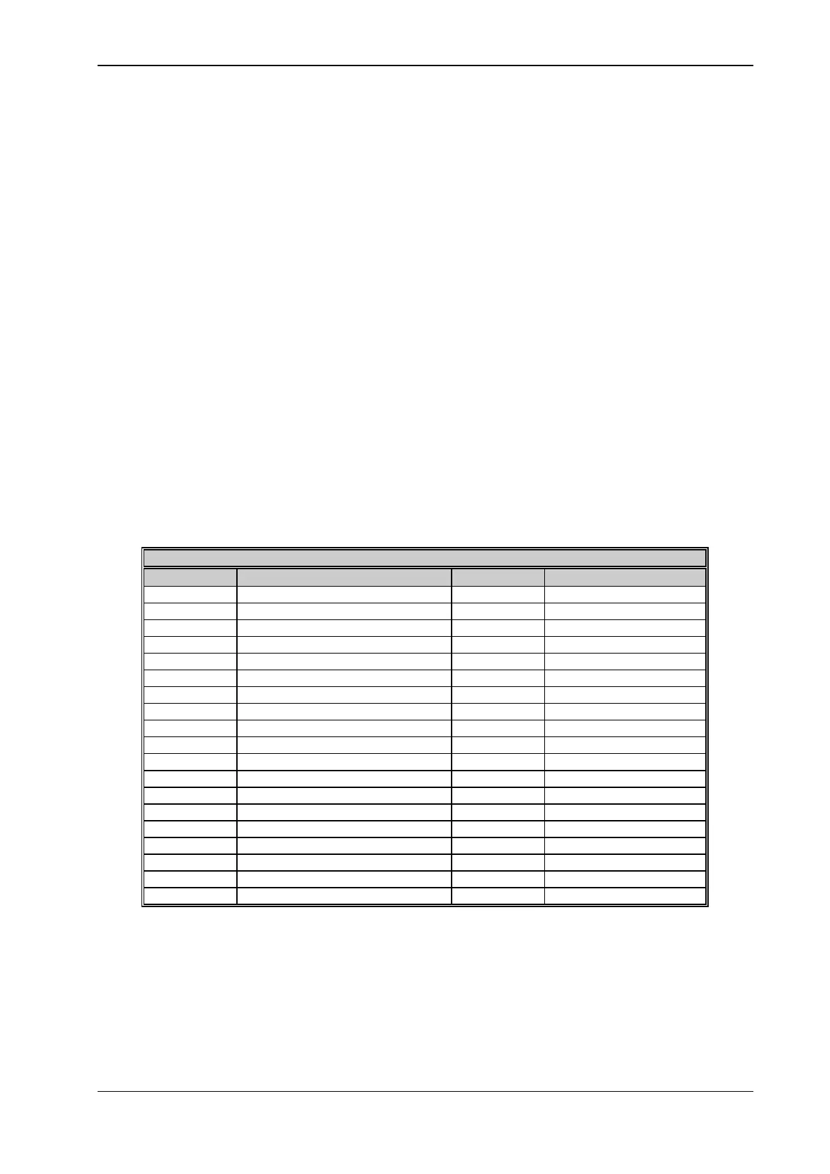
The values that can be set for such parameters are contained in the following table, with the relevant meaning and resulting typology of received datum:
DATA EXCHANGE AREA PARAMETER SETTINGS
-32768@ - 2pu; 32767@ 2 pu
Aux iliary speed feedback
-32768@ - 2pu; 32767@ 2 pu
Additional speed reference
-32768@ - 2pu; 32767@ 2 pu
-32768@ - 2pu; 32767@ 2 pu
Positiv e torque limit reference
-32768@ - 4pu; 32767@ 4 pu
Negativ e torque limit reference
-32768@ - 4pu; 32767@ 4 pu
-32768@ - 4pu; 32767@ 4 pu
-32768@ - 4pu; 32767@ 4 pu
-32768@ - 2pu; 32767@ 2 pu
-32768@ - 2pu; 32767@ 2 pu
-32768@ - 2pu; 32767@ 2 pu
-32768@ - 2pu; 32767@ 2 pu
-32768@ - 2pu; 32767@ 2 pu
-32768@ - 2pu; 32767@ 2 pu
Table 5.8 - Data exchange area parameter settings
5.9.3 Word setting for sent message configuration
The parameters from Area 2 Output Wd 01 Sel [87.52] to Area 2 Output Wd 16 Sel [87.67] are used to assign the meaning of configurable words of
the sent message; these words can be used to:
Send the signals that can normally be displayed through analogue outputs;
Send bit significant information for identification of any tripped hardware and/or software protections;
Send bit significant information concerning Drive status;