Summary
Chapter 1 P. 5
Chapter 2 P. 7
Chapter 3 P. 12
Chapter 4 P. 15
Chapter 5 P. 21
Chapter 6 P. 29
Chapter 7 P. 31
Chapter 8 P. 42
AD700E
22
General information
Important safety information
General Information and Ratings
Mechanical Installation
Operation
Parameters
Analog and Digital Input Macro
Configurations
Power Wiring
Chapter 9 P. 48
Chapter 10 P. 50
Modbus RTU Communications
Technical Data
Trouble Shooting
Chapter 11 P. 54
PREVIOUS VIEW
5.2 EMC FILTER DISCONNECT - 5.3
5
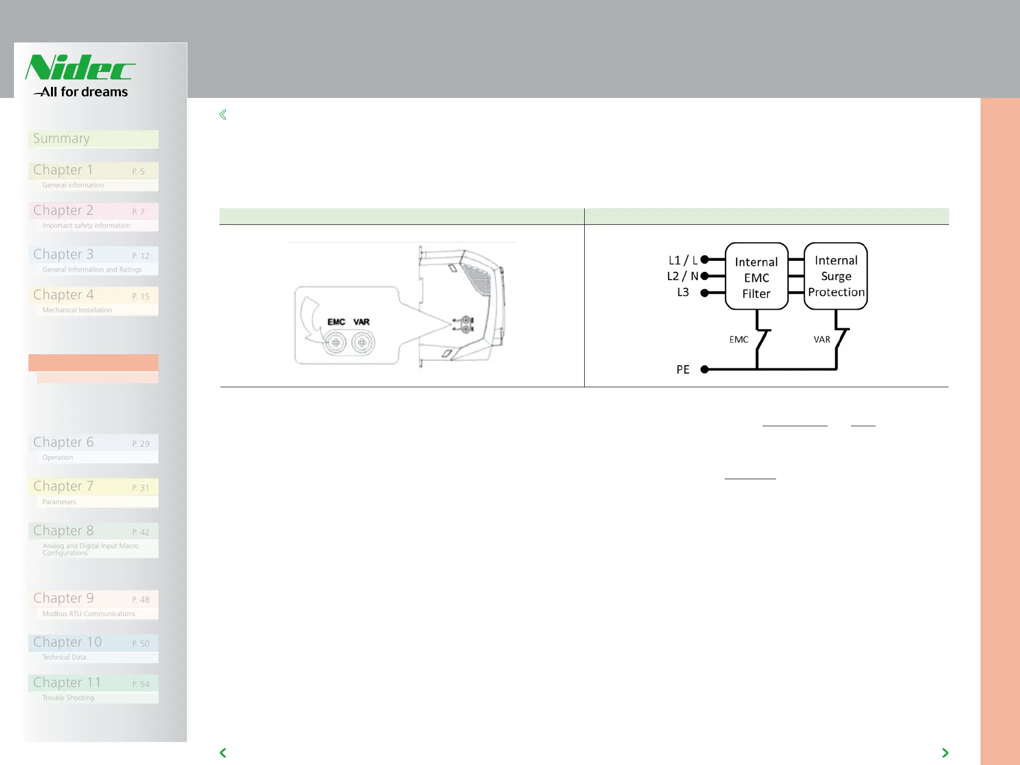
Remove the screws as indicated below Removing the screws breaks the connection
5.2 EMC FILTER DISCONNECT
Drives with an EMC filter have an inherently higher leakage current to
Ground (Earth). For applications where tripping occurs the EMC filter can
be disconnected (on IP20 units only) by completely removing the EMC
screw on the side of the product.
The AD700E product range has input supply voltage surge suppression
components fitted to protect the drive from line voltage transients,
typically originating from lightning strikes or switching of high power
equipment on the same supply.
When carrying out a HiPot (Flash) test on an installation in which the drive
is built, the voltage surge suppression components may cause the test
to fail. To accommodate this type of system HiPot test, the voltage surge
suppression components can be disconnected by removing the VAR screw.
After completing the HiPot test, the screw should be replaced and the
HiPot test repeated. The test should then fail, indicating that the voltage
surge suppression components are once again in circuit.
Shield Termination (Cable Screen)
The safety ground terminal provides a grounding point for the motor
cable shield. The motor cable shield connected to this terminal (drive end)
should also be connected to the motor frame (motor end). Use a shield
terminating or EMI clamp to connect the shield to the safety ground
terminal.
5.3 WIRING PRECAUTIONS
Connect the AD700E according to sections 5.9.1 and 5.9.2, ensuring that
motor terminal box connections are correct. There are two connections
in general: Star and Delta. It is essential to ensure that the motor is
connected in accordance with the voltage at which it will be operated. For
more information, refer to section 5.6 Motor Terminal Box Connections.
It is recommended that the power cabling should be 4-core PVC-insulated
screened cable, laid in accordance with local industrial regulations and
codes of practice.