Summary
Chapter 1 P. 5
Chapter 2 P. 7
Chapter 3 P. 12
Chapter 4 P. 15
Chapter 5 P. 21
Chapter 6 P. 29
Chapter 7 P. 31
Chapter 8 P. 42
AD700E
33
General information
Important safety information
General Information and Ratings
Mechanical Installation
Operation
Parameters
Analog and Digital Input Macro
Configurations
Power Wiring
Chapter 9 P. 48
Chapter 10 P. 50
Modbus RTU Communications
Technical Data
Trouble Shooting
Chapter 11 P. 54
PREVIOUS VIEW
1/6
7
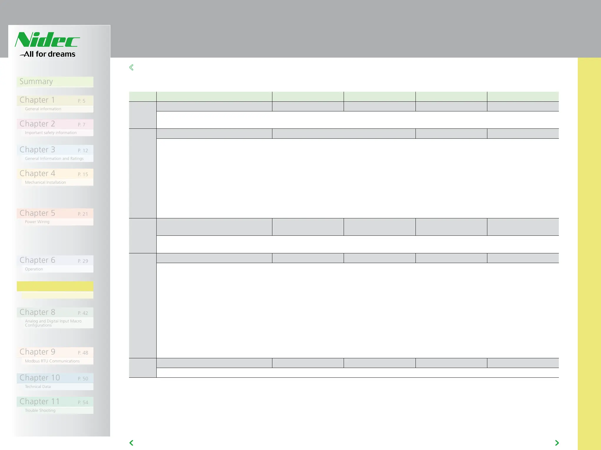
7.2 EXTENDED PARAMETERS
7.2 EXTENDED PARAMETERS
Par Description Minimum Maximum Default Units
P-15 Digital Input Function Select 0 17 0 -
Defines the function of the digital inputs depending on the control mode setting in P-12. See section 8 Analog and Digital Input Macro
Configurations for more information.
P-16 Analog Input 1 Signal Format See Below U0-10 -
U 0-10 = 0 to 10 Volt Signal (Uni-polar). The drive will remain at 0.0Hz if the analog reference after scaling and offset are applied is =<0.0%
b 0-10 = 0 to 10 Volt Signal, bi-directional operation. The drive will operate the motor in the reverse direction of rotation if the analog reference
after scaling and offset are applied is <0.0%. E.g. for bidirectional control from a 0 – 10 volt signal, set P-35 = 200.0%, P-39 = 50.0%
A 0-20 = 0 to 20mA Signal
t 4-20 = 4 to 20mA Signal, the Answer Drives will trip and show the fault code 4-20f if the signal level falls below 3mA
r 4-20 = 4 to 20mA Signal, the Answer Drives will run at Preset Speed 1 (P-20) if the signal level falls below 3mA
t 20-4 = 20 to 4mA Signal, the Answer Drives will trip and show the fault code 4-20f if the signal level falls below 3mA
r 20-4 = 20 to 4mA Signal, the Answer Drives will run at Preset Speed 1 (P-20) if the signal level falls below 3mA
U 10-0 = 10 to 0 Volt Signal (Uni-polar). The drive will operate at Maximum Frequency / Speed if the analog reference after scaling and offset
are applied is =<0.0%
P-17 Maximum Effective Switching
Frequency
4 32 8 / 16 kHz
Sets maximum effective switching frequency of the drive. If “rEd” is displayed, the switching frequency has been reduced to the level in P00-32
due to excessive drive heatsink temperature.
P-18 Output Relay Function Select 0 7 1 -
Selects the function assigned to the relay output. The relay has two output terminals, Logic 1 indicates the relay is active, and therefore
terminals 10 and 11 will be connected.
0 : Drive Enabled (Running). Logic 1 when the motor is enabled
1 : Drive Healthy. Logic 1 when power is applied to the drive and no fault exists
2 : At Target Frequency (Speed). Logic 1 when the output frequency matches the setpoint frequency
3 : Drive Tripped. Logic 1 when the drive is in a fault condition
4 : Output Frequency >= Limit. Logic 1 when the output frequency exceeds the adjustable limit set in P-19
5 : Output Current >= Limit. Logic 1 when the motor current exceeds the adjustable limit set in P-19
6 : Output Frequency < Limit. Logic 1 when the output frequency is below the adjustable limit set in P-19
7 : Output Current < Limit. Logic 1 when the motor current is below the adjustable limit set in P-19
8 : Analog Input 2 > Limit. Logic 1 when the signal applied to analog input 2 exceeds the adjustable limit set in P-19
9 : Drive Ready to Run. Logic 1 when the drive is ready to run, no trip present.
P-19 Relay Threshold Level 0.0 200.0 100.0 %
Adjustable threshold level used in conjunction with settings 4 to 8 of P-18