Summary
Chapter 1 P. 5
Chapter 2 P. 7
Chapter 3 P. 12
Chapter 4 P. 15
Chapter 5 P. 21
Chapter 6 P. 29
Chapter 7 P. 31
Chapter 8 P. 42
AD700E
18
General information
Important safety information
General Information and Ratings
Mechanical Installation
Operation
Parameters
Analog and Digital Input Macro
Configurations
Power Wiring
Chapter 9 P. 48
Chapter 10 P. 50
Modbus RTU Communications
Technical Data
Trouble Shooting
Chapter 11 P. 54
PREVIOUS VIEW
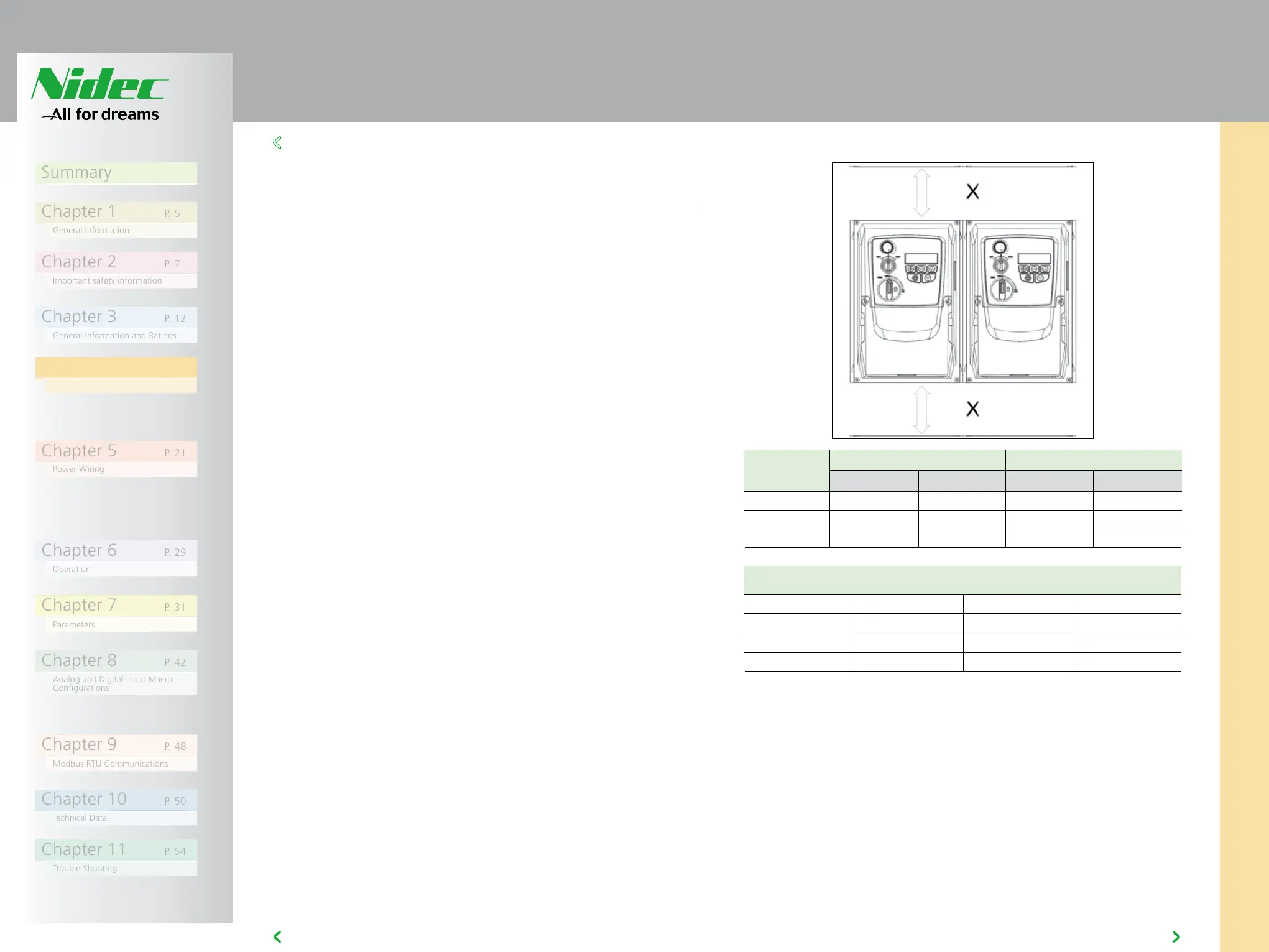
4.6 GUIDELINES FOR MOUNTING (IP66 UNITS)
4
4.6 GUIDELINES FOR MOUNTING (IP66 UNITS)
• Before mounting the drive, ensure that the chosen location meets the
environmental condition requirements for the drive shown in section 10.1
• The drive must be mounted vertically, on a suitable flat surface
• The minimum mounting clearances as shown in the table below must be
observed
• The mounting site and chosen mountings should be sufficient to support
the weight of the drives
• Using the drive as a template, or the dimensions shown above, mark the
locations required for drilling
• Suitable cable glands to maintain the ingress protection of the drive are
required. Gland holes for power and motor cables are pre-moulded into
the drive enclosure, recommended gland sizes are shown above. Gland
holes for control cables may be cut as required.
NOTE:
Typical drive heat losses are approximately 3% of operating load
conditions.
Above are guidelines only and the operating ambient temperature of the
drive MUST be maintained at all times.
Drive Size X Above & Below Y Either Side
mm in mm in
1 200 7.87 10 0.39
2 200 7.87 10 0.39
3 200 7.87 10 0.39
Cable Gland Sizes
Drive Size Power Cable Motor Cable Control Cables
1 M20 (PG13.5) M20 (PG13.5) M20 (PG13.5)
2 M25 (PG21) M25 (PG21) M20 (PG13.5)
3 M25 (PG21) M25 (PG21) M20 (PG13.5)