Summary
Chapter 1 P. 5
Chapter 2 P. 7
Chapter 3 P. 12
Chapter 4 P. 15
Chapter 5 P. 21
Chapter 6 P. 29
Chapter 7 P. 31
Chapter 8 P. 42
AD700E
25
General information
Important safety information
General Information and Ratings
Mechanical Installation
Operation
Parameters
Analog and Digital Input Macro
Configurations
Power Wiring
Chapter 9 P. 48
Chapter 10 P. 50
Modbus RTU Communications
Technical Data
Trouble Shooting
Chapter 11 P. 54
PREVIOUS VIEW
5.7 MOTOR THERMAL OVERLOAD PROTECTION - 5.7.1 - 5.7.2 - 5.8
5
5.7 MOTOR THERMAL OVERLOAD PROTECTION
5.7.1 INTERNAL THERMAL OVERLOAD PROTECTION
The drive has an in-built motor thermal overload function; this is in the
form of an “I.t-trP” trip after delivering >100% of the value set in P-08 for
a sustained period of time (e.g. 150% for 60 seconds).
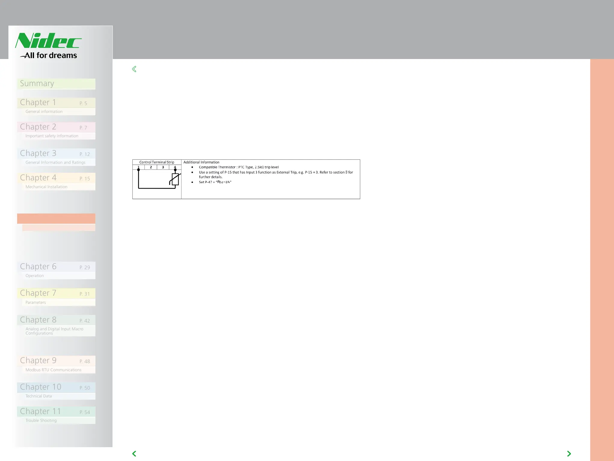
5.7.2 MOTOR THERMISTOR CONNECTION
Where a motor thermistor is to be used, it should be connected as follows:
5.8 CONTROL TERMINAL WIRING
• All analog signal cables should be suitably shielded. Twisted pair cables
are recommended.
• Power and Control Signal cables should be routed separately where
possible, and must not be routed parallel to each other.
• Signal levels of different voltages e.g. 24 Volt DC and 110 Volt AC,
should not be routed in the same cable.
• Maximum control terminal tightening torque is 0.5Nm.
• Control Cable entry conductor size: 0.05 – 2.5mm2 / 30 – 12 AWG.