Summary
Chapter 1 P. 5
Chapter 2 P. 7
Chapter 3 P. 12
Chapter 4 P. 15
Chapter 5 P. 21
Chapter 6 P. 29
Chapter 7 P. 31
Chapter 8 P. 42
AD700E
49
General information
Important safety information
General Information and Ratings
Mechanical Installation
Operation
Parameters
Analog and Digital Input Macro
Configurations
Power Wiring
Chapter 9 P. 48
Chapter 10 P. 50
Modbus RTU Communications
Technical Data
Trouble Shooting
Chapter 11 P. 54
PREVIOUS VIEW
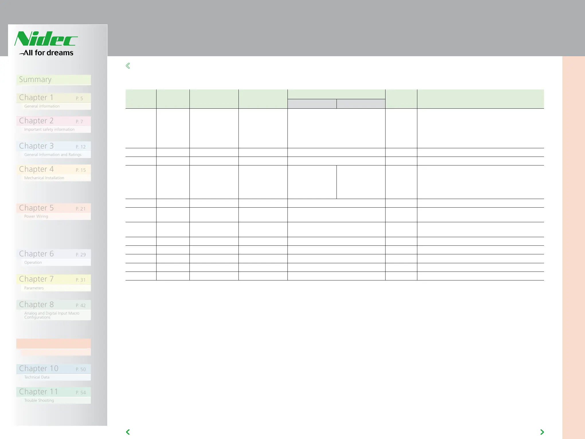
9.5 MODBUS REGISTER MAP
9
9.5 MODBUS REGISTER MAP
All user configurable parameters are accessible as Holding Registers, and
can be Read from or Written to using the appropriate Modbus command.
The Register number for each parameter P-04 to P-047 is defined as 128 +
Parameter number, e.g. for parameter P-15, the register number is 128 +
15 = 143. Internal scaling is used on some parameters, for further details,
please contact your NIDEC representative www.nidec-industrial.com
Register
Number
Par. Type Supported
Commands
Function Range Explanation
Low Byte High Byte
1 - R/W 03,06 Drive Control Command 0..3 16 Bit Word.
Bit 0 : Low = Stop, High = Run Enable
Bit 1 : Low = Decel Ramp 1 (P-04), High = Decel Ramp
2 (P-24)
Bit 2 : Low = No Function, High = Fault Reset
Bit 3 : Low – No Function, High = Coast Stop Request
2 - R/W 03,06 Modbus Speed reference setpoint 0..5000 Setpoint frequency x10, e.g. 100 = 10.0Hz
4 - R/W 03,06 Acceleration and Deceleration Time 0..60000 Ramp time in seconds x 100, e.g. 250 = 2.5 seconds
6 - R 03 Error code Drive status Low Byte = Drive Error Code, see section 10.1
High Byte = Drive Status as follows :
0 : Drive Stopped
1: Drive Running
2: Drive Tripped
7 R 03 Output Motor Frequency 0..20000 Output frequency in Hz x10, e.g. 100 = 10.0Hz
8 R 03 Output Motor Current 0..480 Output Motor Current in Amps x10, e.g. 10 = 1.0
Amps
11 - R 03 Digital input status 0..15 Indicates the status of the 4 digital inputs
Lowest Bit = 1 Input 1
20 P00-01 R 03 Analog Input 1 value 0..1000 Analog input % of full scale x10, e.g. 1000 = 100%
21 P00-02 R 03 Analog Input 2 value 0..1000 Analog input % of full scale x10, e.g. 1000 = 100%
22 P00-03 R 03 Speed Reference Value 0..1000 Displays the setpoint frequency x10, e.g. 100 = 10.0Hz
23 P00-08 R 03 DC bus voltage 0..1000 DC Bus Voltage in Volts
24 P00-09 R 03 Drive temperature 0..100 Drive heatsink temperature in ºC