Summary
Chapter 1 P. 5
Chapter 2 P. 7
Chapter 3 P. 12
Chapter 4 P. 15
Chapter 5 P. 21
Chapter 6 P. 29
Chapter 7 P. 31
Chapter 8 P. 42
AD700E
51
General information
Important safety information
General Information and Ratings
Mechanical Installation
Operation
Parameters
Analog and Digital Input Macro
Configurations
Power Wiring
Chapter 9 P. 48
Chapter 10 P. 50
Modbus RTU Communications
Technical Data
Trouble Shooting
Chapter 11 P. 54
PREVIOUS VIEW
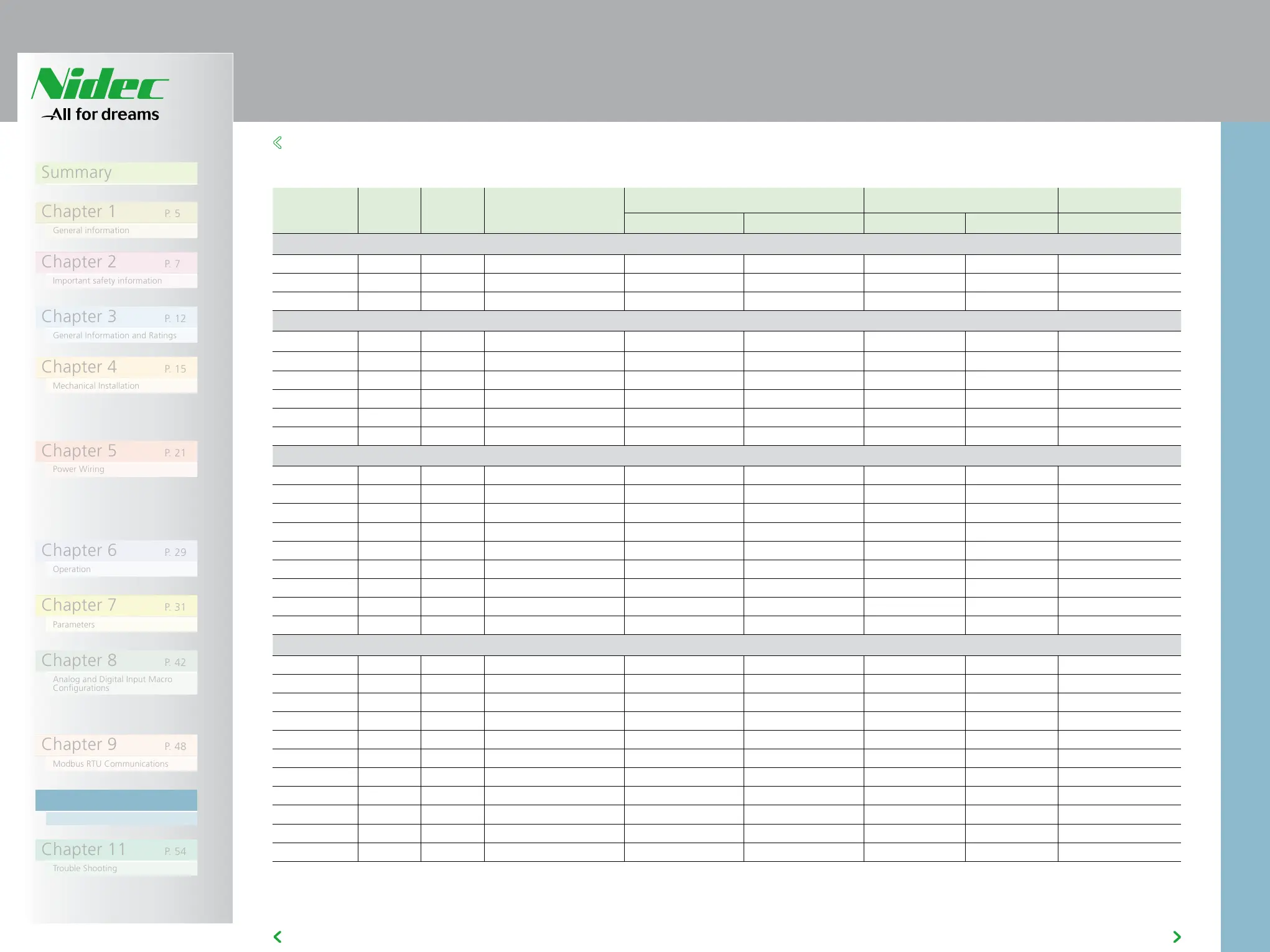
10.2 RATING TABLES
NOTE: Cable sizes shown are the maximum possible that may be
connected to the drive. Cables should be selected according to local
wiring codes or regulations at the point of installation
Frame Size kW HP Input Current Fuse / MCB (Type B) Maximum Cable Size Output Current
Non UL UL mm AWG A
110 - 115 (+ / - 10%) V 1 Phase Input, 230V 3 Phase Output (Voltage Doubler)
1 0.37 0.5 7.8 10 10 8 8 2.3
1 0.75 1 15.8 25 20 8 8 4.3
2 1.1 1.5 21.9 32 30 8 8 5.8
200 - 240 (+ / - 10%) V 1 Phase Input, 3 Phase Output
1 0.37 0.5 3.7 10 6 8 8 2.3
1 0.75 1 7.5 10 10 8 8 4.3
1 1.5 2 12.9 16 17.5 8 8 7
2 1.5 2 12.9 16 17.5 8 8 7
2 2.2 3 19.2 25 25 8 8 10.5
3 4 5 29.2 40 40 8 8 16
200 - 240 (+ / - 10%) V 3 Phase Input, 3 Phase Output
1 0.37 0.5 3.4 6 6 8 8 2.3
1 0.75 1 5.6 10 10 8 8 4.3
1 1.5 2 9.5 16 15 8 8 7
2 1.5 2 8.9 16 15 8 8 7
2 2.2 3 12.1 16 17.5 8 8 10.5
3 4 5 20.9 32 30 8 8 18
3 5.5 7.5 26.4 40 35 8 8 24
4 7.5 10 33.3 40 45 16 5 30
4 11 15 50.1 63 70 16 5 46
380 - 480 (+ / - 10%)V 3 Phase Input, 3 Phase Output
1 0.75 1 3.5 6 6 8 8 2.2
1 1.5 2 5.6 10 10 8 8 4.1
2 1.5 2 5.6 10 10 8 8 4.1
2 2.2 3 7.5 16 10 8 8 5.8
2 4 5 11.5 16 15 8 8 9.5
3 5.5 7.5 17.2 25 25 8 8 14
3 7.5 10 21.2 32 30 8 8 18
3 11 15 27.5 40 35 8 8 24
4 15 20 34.2 40 45 16 5 30
4 18.5 25 44.1 50 60 16 5 39
4 22 30 51.9 63 70 16 5 46
10.2 RATING TABLES
10