Safety
information
Product
information
Mechanical
installation
Electrical
installation
Getting
started
Running the
motor
Drive parameters Communications Diagnostics Technical data
UL Listing
Information
48 Commander S100 User Guide
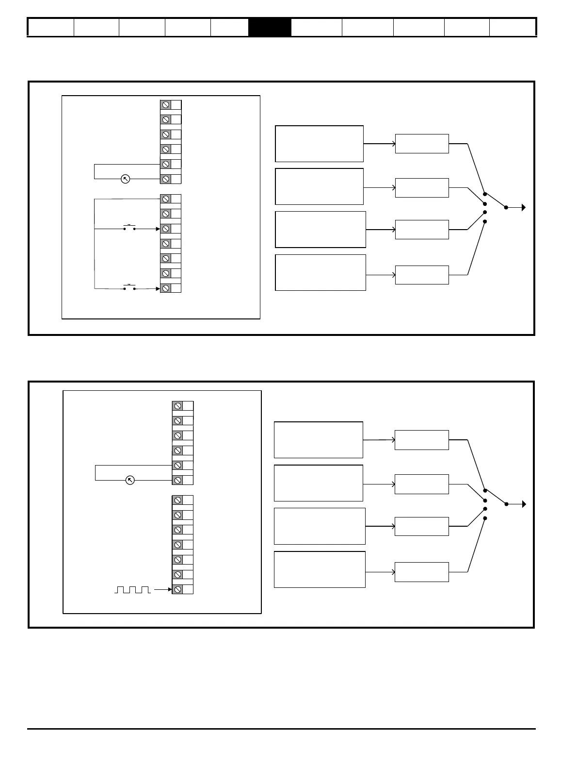
P0.05 = Terminal Speed Control (6)
The Up/Down Percentage (P1.18) is used as a frequency reference where 0 % = Minimum Frequency Limit (P0.01); and 100 % = Maximum
Frequency Limit (P0.02). Up/Down Percentage (P1.18) is increased by a momentary switch on digital input 5 and decreased by a momentary switch
on digital input 1.
P0.05 = Frequency Input (7)
A frequency input on digital input 5 (terminal 15) provides the frequency reference where 0 kHz = Minimum Frequency Limit (P2.01) and 100 kHz =
Maximum Frequency Limit (P2.02). To reduce the maximum frequency input on digital input 5, set T15 Frequency Input Maximum Input (P6.31) to the
required level as a percentage of 100 kHz. (e.g. set to 50 % if the maximum frequency input should be 50 kHz)
Not Configured
Not Configured
Not Configured
Up/Down
Percentage (P1.18)
Reference 1
Reference 2
Reference 3
Reference 4
1
2
3
4
9
+10 V Output
0 V
5
0 V
6
Analog output
10
11
12
13
14
15
+24 V Output
0 V
DI 2
DI 3
DI 4
Terminal Up/Down (P0.05 = 6)
Decrease speed (DIO 1)
Increase speed (DI 5)
Analog input 1 (AI1)
Analog input 2 (AI2)
Not Configured
Not Configured
Not Configured
T15 Frequency Input
Percentage (P1.17)
Reference 1
Reference 2
Reference 3
Reference 4
1
2
3
4
9
+10 V Output
0 V
5
0 V
6
Analog output
10
11
12
13
14
15
+24 V Output
0 V
DIO 1
DI 2
DI 3
DI 4
Frequency input (P0.05 = 7)
Analog input 2 (AI2)
Frequency input (DI 5)
Analog input 1 (AI1)