Safety
information
Product
information
Mechanical
installation
Electrical
installation
Getting started
Running the
motor
Drive
parameters
Communications Diagnostics Technical data
UL Listing
Information
Commander S100 User Guide 79
P3.20 Reverse Motor Direction
Range: 0 to 1 Default: 0 (Normal Operation)
If the motor direction does not match the required forward and reverse control signals, this parameter can be used to change the motor direction
without the need to swap output cables. Changes to this parameter will only take effect when the drive is not running.
This reverses the output phase sequence for the selected forward and reverse directions which is non-standard.
P3.21 Thermal Protection Action
Range: 0 to 4 Default: 3 (Limit with Save)
Set the required thermal protection action as below:
If any of the current limiting modes are selected, both Motor Thermal Percentage (P1.22) and Drive Thermal Percentage (P1.23) will cause the
current limit to be reduced. If thermal limiting is active, bit 2 is set in Drive Status Indicators (P1.10).
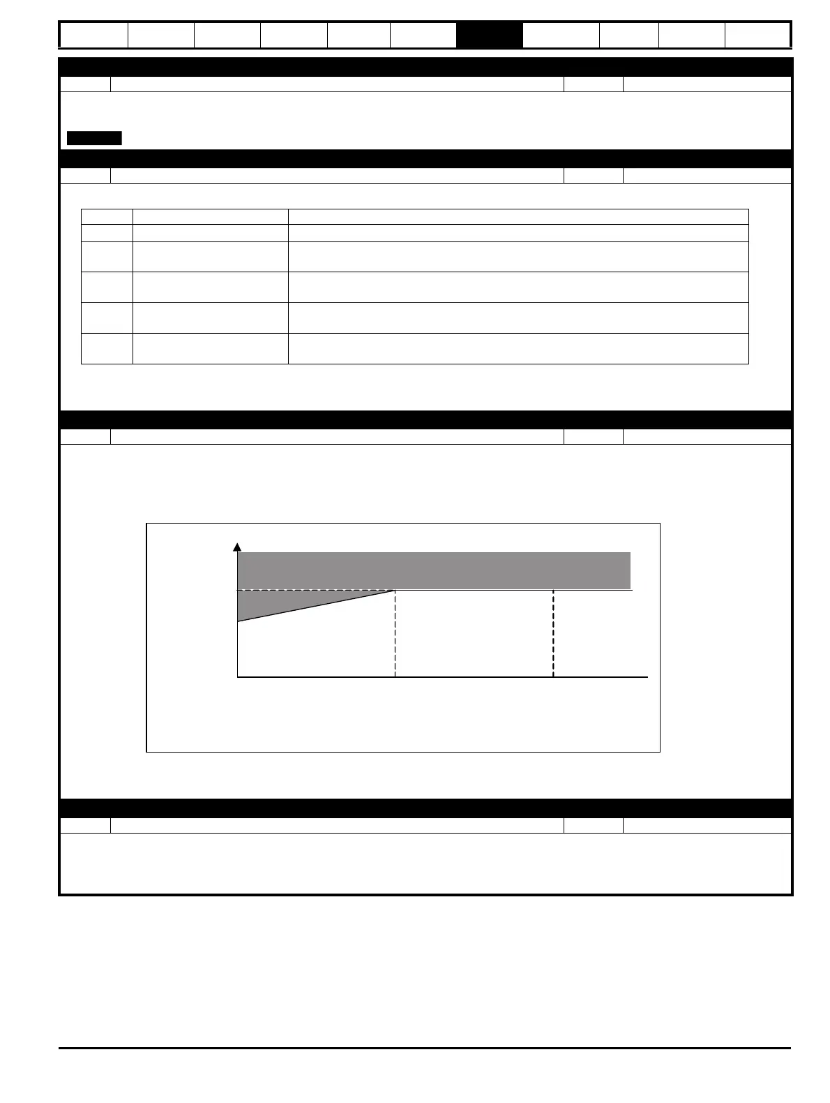
P3.22 Low Frequency Thermal Protection
Range: 0 to 1 Default: 1 (On)
If a motor with a shaft mounted fan is likely to run with high loads at low frequencies, then this parameter should be set to 1 (On) to protect the
motor thermally. The drive does this by reducing the level at which it considers the motor to be in overload to 70 % of the motor rated current when
operating below 50 % of the motor's rated frequency.
Figure 7-11 Low Frequency Thermal Protection = On (1)
P3.23 Current Controller Gain
Range: 0 to 250 Default: 40
Used to adjust the gain of the current controller. This does not normally need to be adjusted, but it can be reduced if there is evidence of motor
noise during current limiting. Increasing the value may be required if Standard Ramp (1) or Ramp + Motor Loss (2) are being used in Deceleration
Ramp Type (P2.11) with a high inertia load, or if Supply Loss Action (P4.08) > 0, as the increased gain will help the control of the D.C. link voltage
during these operations.
Value Thermal Protection Action Description
0
Disabled No motor thermal protection but drive thermal protection is still active.
1
Error with Save
Drive generates an Error when Limit reached. Motor and Drive thermal protection
percentages are stored at power down.
2
Error
Drive generates an Error when Limit reached. Motor and Drive thermal protection
percentages start at 0 % at power up.
3
Limit with Save
Current is limited if drive or motor thermal percentage approaches 100 %. Motor and Drive
percentages are stored at power down.
4
Limit
Current is limited if drive or motor thermal percentage approaches 100 %. Motor and Drive
percentages start at 0 % at power up.
70
10050
Percentage of
Motor Rated
Current (P3.02)
Percentage of Rated Frequency (P3.15)
100
Overload