SM-Applications Modules & Motion Processors User Guide 19
Issue Number: 4
Safety
Information
Introduction
Installation
Getting
Started
Parameters
DPL
Programming
Communications
Freeze and
Marker
CTSync
Inter-option
Synchronization
Diagnostics
Migration
Guide
Quick
Reference
Index
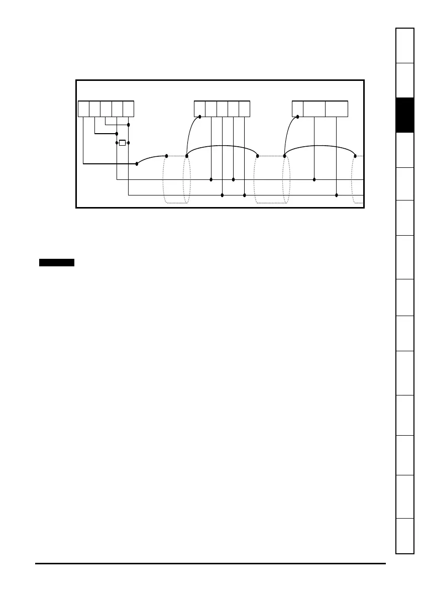
3.7.2 2 Wire EIA-RS485 Network
The diagram below shows the connections required for a 2 wire EIA-RS485 network,
using a master controller with an EIA-RS485 port. SM-Applications Modules & Motion
Processors can be configured to act as master controllers, but this requires DPL
programming to control the network.
An EIA-RS232 to EIA-RS485 converter with “intelligent transceiver switching” (also
known as “magic” EIA-RS485 converters) is required to allow a standard PC serial port
to communicate with a 2 wire EIA-RS485 network. An example of a “magic” converter is
the MA485F converter from Amplicon.
3.7.3 Grounding
It is recommended for safety that the shield of the communications cable be connected
by a low-inductance path to a ‘clean’ earth point. This must only be done at one point.
3.7.4 Routing of the cable
A data communications cable should not run parallel to any power cables, especially
ones that connect drives to motors. If parallel runs are unavoidable, ensure a minimum
spacing of 300 mm (1 foot) between the communications cable and the power cable.
Cables crossing one another at right-angles are unlikely to give trouble. The maximum
cable length for a EIA-RS485 link is 1200 metres (4,000 feet). This is at low baud rates
only. The higher the baud rate the lower the maximum cable length.
3.7.5 Termination
When a long-distance multi-drop EIA-RS485 system is used, the transmit and receive
pairs should have a termination resistor of 120 fitted across them in order to reduce
signal reflections. However, at the lower data rates this is not so critical.
A “magic” converter is not required if the master controller has an RTS control output.
This output is enabled when the master is transmitting, and disabled when the master is
not transmitting. Control Techniques software packages (UniSoft, MentorSoft and
SystemWise) do NOT switch the RTS line.
0V / Rx Rx / Tx Tx
12345
SM-Applications Modul e
Sl a ve
Co mmander SE
Sl ave
0V TxRxB TxRxA
37 2
0V / Rx Rx / Tx Tx
12345
Master
120 0.25W
termination resi stor
 Loading...