SM-Applications Modules & Motion Processors User Guide 71
Issue Number: 4
Safety
Information
Introduction Installation
Getting
Started
Parameters
DPL
Programming
Communications
Freeze and
Marker
CTSync
IInter-option
Synchronization
Diagnostics
Migration
Guide
Quick
Reference
Index
+1.2345 is written to a parameter with one decimal place the result is 1.2, if +1.2 is
written to a parameter with three decimal places the result is 1.200). It should be
noted that parameters can only have 0, 1, 2, 3, 4, 5, or 6 decimal places.
5. The data field can contain up to 10 numbers, but the value (even ignoring decimal
points) must not exceed the range -2
31
to 2
31
-1.
If the parameter is written successfully an Acknowledge character (Ctrl & F) is returned.
If the parameter does not exist, the value written exceeds the range for that parameter
or the data field rules are not obeyed, a Not acknowledge character (Ctrl & U) is
returned.
The checksum is derived by exclusive ORing the message bytes (characters) together
excluding the STX character and the checksum, i.e. Checksum = M1 ^ M2 ^ P1 ^ P2 ^
D1 ^ D2 ^ ..... Dn ^ ETX. The checksum is an unsigned 8bit value and if this value is less
than 32 then 32 is added to it.
6.1.1.3 Second Processor address
The Second Processor will only act on messages received where the full address
matches the address of the Second Processor or the group address in the message (1
st
digit) matches the 1
st
digit of the address of Second Processor or the address in the
message is a broadcast (0). Broadcast messages are used to write data to multiple
nodes.
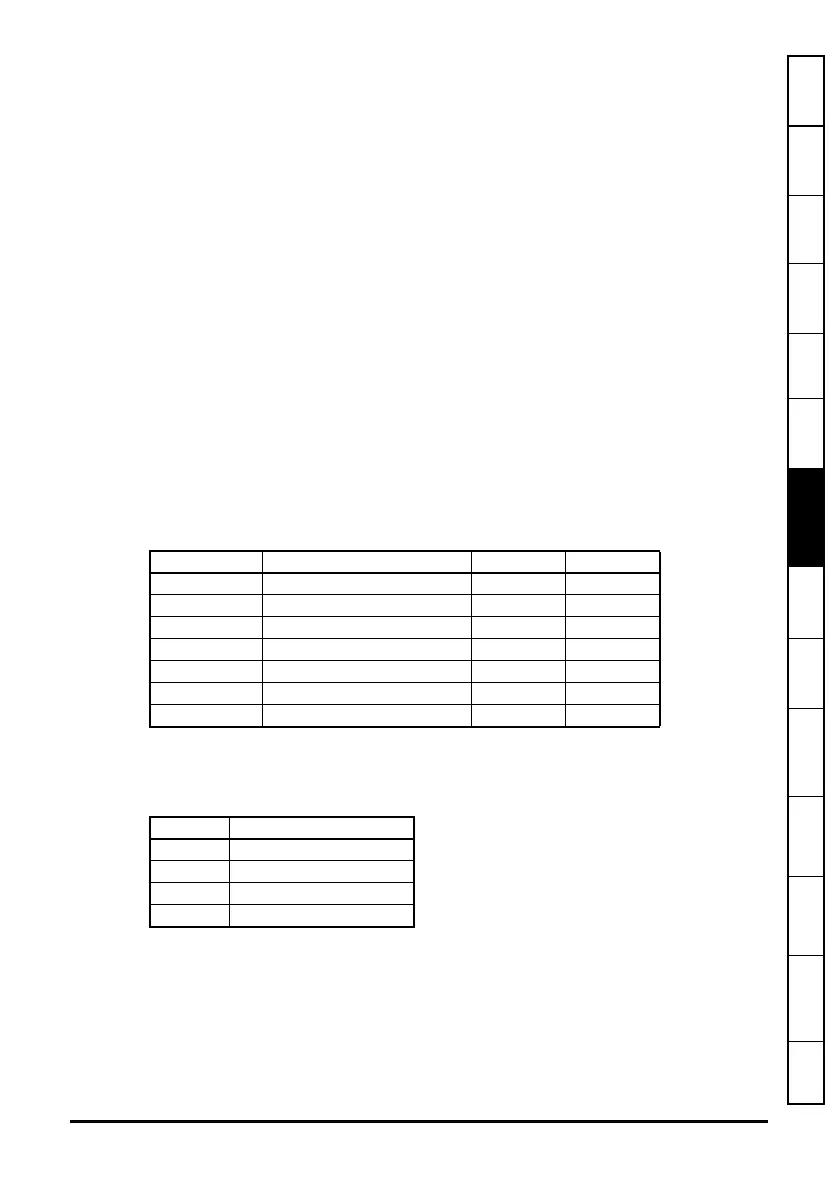
6.1.1.4 Control Characters
6.1.2 Modbus-RTU
Both slave and master modes of the Modicon Modbus-RTU protocol are supported.
In RTU slave mode, the following function codes are supported:
The maximum number of registers that can be read/written simultaneously is 20.
Drive parameters are mapped to Modbus registers as
40000 + Menu×100 + Parameter.
For example, Pr
01.21 will be register number 40121.
Table 6-4 Summary of control characters
Character Description ASCII code Ctrl code
STX Start of text 02 B
ETX End of text 03 C
EOT End of transmission 04 D
ENQ Enquiry 05 E
ACK Acknowledge 06 F
BS Backspace 08 H
NAK Not acknowledge 15 U
Function Description
FC3 Read multiple registers
FC6 Preset single registers
FC16 Preset multiple registers
FC23 Read/write multiple registers
 Loading...