SPDM CONTROL PANEL 1 – TECHNICAL DATA
NIDEC ASI S.P.A. – SPDM CONTROL PANEL USER MANUAL
IMSPDCB2EN 11
1 TECHNICAL DATA
1.1 Identification
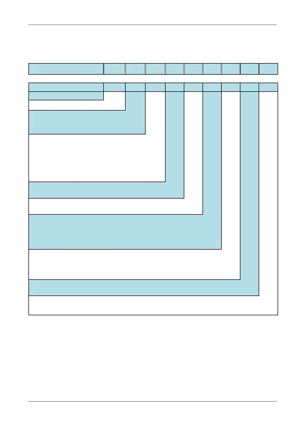
SPDMBX S x x B x x x x ..
1,2,3,4,5,6 7 8 9 10 11 12 13 14 15.16
Product Series
Control board S = "System2" control board
Operating mode
U = 2 quadrants operation
R = 4 quadrants operation
F = 2 or 4 quadrants with fiber-optic
Power supply
voltage
G = 380-500 V
H = 600 V
K = 690 V
W= 750 V
M = 850
N = 950
Version
B = box (290w x 530h x 178d)
P = panel (555w x 310h x 78d)
Keypad
N = Not installed
H = Installed
Communication
Expansions
N = Not installed
E = EtherNet/IP (GSB40A-EtherNet/IP board)
I = PROFINET IO (GSB40A-PROFINET board)
Note: PROFIBUS DP and Modbus TCP are already included in control board
SYSTEM2
Expansion Boards
N = Not installed
A = Analog expansion board (GEOSA)
T = Analog expansion board for tachogenerator (GTACA)
E = Encoder expansion board (SYSENC)
Safe Torque Off
function
N = Not installed
T = STO board installed
Suffix
(Special versions)
62 = Acid/marine environmental: special tin
m) and boards with double
coating
80 = I/O Expansion (Relè card)
(*) Fiber optic connection kit and electrical cable kit are not included.