SPDM CONTROL BOX 2 – COMPOSITION
NIDEC ASI S.P.A. – SPDM CONTROL BOX USER MANUAL
IMSPDCB2EN 19
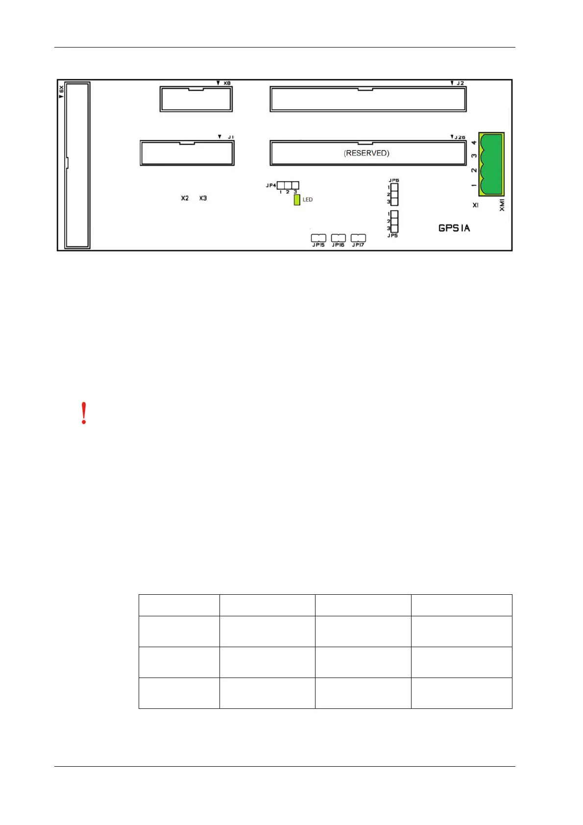
2.4.1 GPSIA Layout
2.4.2 Connectors
Terminal block XM1
1-2 External synchronization voltage (Vuv), max. peak amplitude ±12V; nominal value 6 Vrms.
3-4 External synchronization voltage (Vwu) max. peak amplitude ±12V; nominal value 6 Vrms.
Connector J1 For connection with connector J1 of the SYSTEM2 board.
Connector J2 For connection with connector J2 of the SYSTEM2 board.
Connector J26 Reserved.
Connector X8 For connection with connector X8-2 of the GIFOA board.
Connector X9 For connection with connector X9 of the BPR50 board.
the connection of the connector J2 of SYSTEM2 board: this connector can be
connected only to J2 of GPSIA. To avoid damages to the SYSTEM2 board, don’t use the
reserved connector J26 of GPSIA.
2.4.3 Jumpers
Jumper JP4 Chopping function. On position 2-3 (default) the pulses generated by SYSTEM2 and sent to GIFOA remain “solid”.
On position 1-2, the firing pulses generated by SYSTEM2 board are “chopped” (train pulse), .
Jumper JP5 Synchronization voltage Vuv selection. On position 1-2 (default), the synchronization voltage Vuv is taken from
internal transducer (from BPR50 board). On position 2-3 the synchronization voltage Vuv is taken from terminal
board XM1-1/XM1-2.
Jumper JP6 Synchronization voltage Vwu selection. On position 1-2 (default), the synchronization voltage Vwu is taken from
internal transducer (from BPR50 board). On position 2-3 the synchronization voltage Vwu is taken from terminal
board XM1-3/XM1-4.
Jumper JP15,16,17 Selection of the measured DC voltage range. The voltage range depends on the external resistor according with
the following table
470k
External resistors = 1M External resistors = 1.5M
16 open
17 open
160V < Va < 300V 200V < Va < 380V 240V < Va < 450V
16 closed
17 open
300V < Va< 570V 380V < Va< 720V 450V < Va< 860V
16 open
17 closed
570V < Va< 900V 720V < Va< 1100V 860V < Va< 1300V