3 – SYSTEM2 BOARD SPDM CONTROL BOX
NIDEC ASI S.P.A. – SPDM CONTROL BOX USER MANUAL
46 IMSPDCB2EN
3 POLES Signal
1 24V
2 GND
3 7,5V
Table 3-23: signal assignment of the connector J2 module SYSENC.
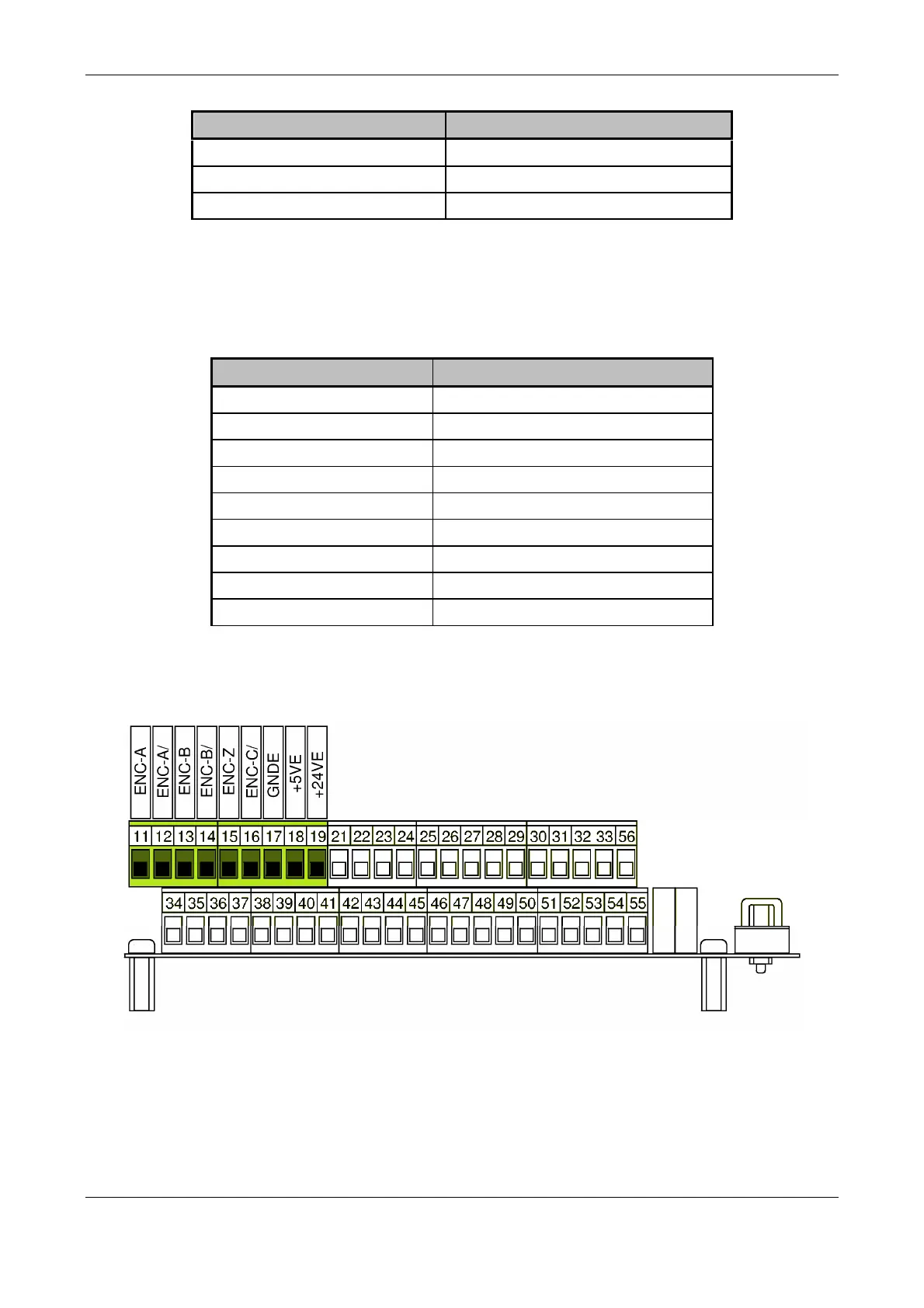
3.4.5 J3, encoder inputs removable terminal blocks
The table below shows the assignment of the signals of the encoder inputs to removable terminal 9-pin connector on the encoder interface
mezzanine.
Terminal Signal
11 ENC-A
12 ENC-A/
13 ENC-B
14 ENC-B/
15 ENC-Z
16 ENC-Z/
17 GNDE
18 +5VE
19 +24VE
Table 3-24: Signal assignment of the connector J3 module SYSENC.
In the figure below you can see the location and number of encoder interface terminals with respect to the removable terminal block of card
SYSTEM2
Figure 3-10: side view of the terminals of Mezzanine Encoder.
3.4.6 DL1, monitor of power supply +24V
The LED DL1 monitors the presence of a + 24V voltage on terminal 19 of J3. It lights up when power supply is applied to the mezzanine.