SPDM CONTROL BOX 3 – SYSTEM2 BOARD
NIDEC ASI S.P.A. – SPDM CONTROL BOX USER MANUAL
IMSPDCB2EN 45
Figure 3-8: side view of the Mezzanine Encoder mounting.
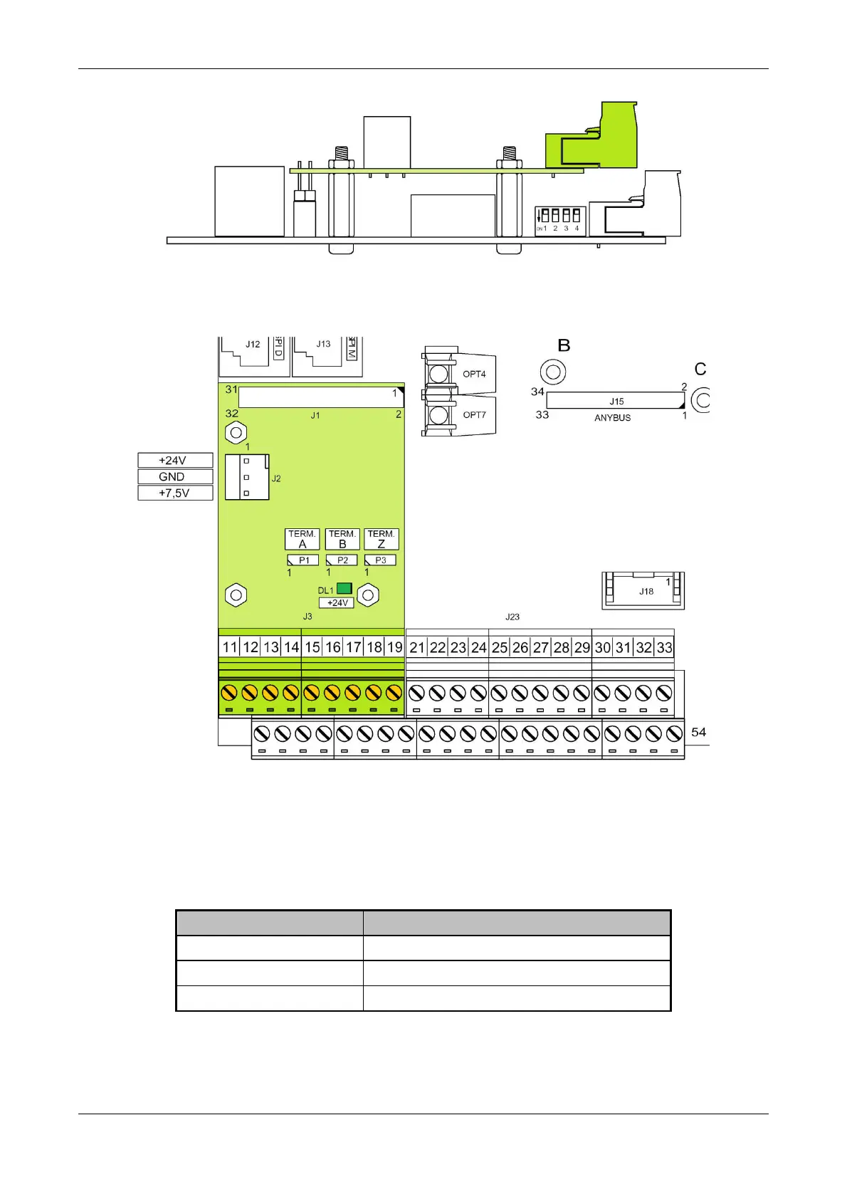
Figure 3-9: Top view of the Mezzanine Encoder mounting.
3.4.3 P1, P2 e P3, jumpers for the differential lines termination
The three pins jumpers P1, P2 and P3 allow to insert the termination of the three encoder lines available on connector with removable terminals J3
“SYSENC” module (respectively line A, line B and line Z). It is possible to insert two different values of termination resistors, 110 or 220. The
table below shows the possible configurations.
Config. P1,P2 e P3 State of the line
open Line not terminated
1-2
Line terminated at 220
2-3
Line terminated at 110
Table 3-22: Configuration of jumpers P1, P2 and P3 on module SYSENC.
3.4.4 J2, connector for power supply of module SYSENC.