SPDM CONTROL BOX 3 – SYSTEM2 BOARD
NIDEC ASI S.P.A. – SPDM CONTROL BOX USER MANUAL
IMSPDCB2EN 39
Terminal Signal Description
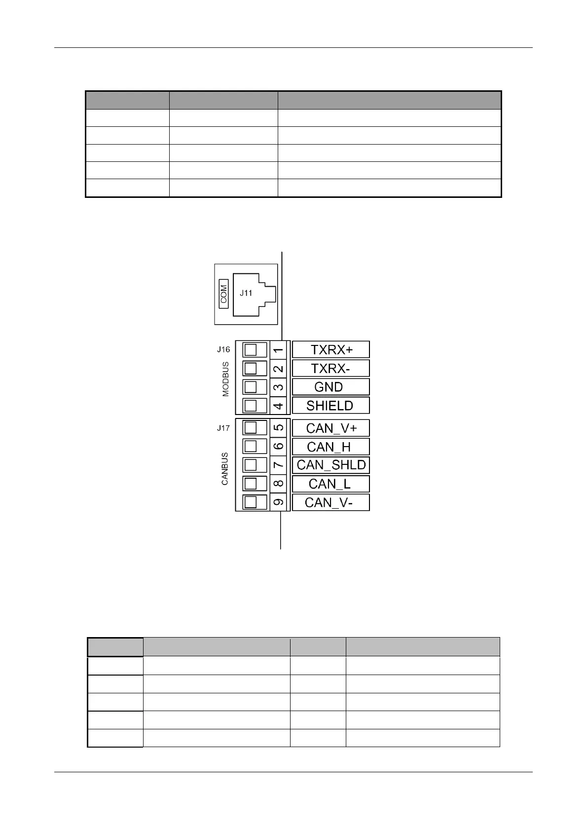
5 CAN_V+ Power supply + 24V
6 CAN_H Line CAN_H
7 CAN_SHLD Cable shield
8 CAN_L Line CAN_L
9 CAN_V- Ground /0V/V-
Table 3-17: connector J17 signal assignment
Below is a detailed illustration of the terminals J16 and J17.
Figure 3-4: Particular of the connectors J16 and J17
3.2.4 J18, auxiliary Opto-isolated digital outputs
The table below shows the assignment of the auxiliary opto-isolated outputs signals to the connector pins DIL10.
Each of the 7 digital output is an open emitter with maximum source current of 50mA and 24V.
Pin Signal Pin Signal
1 ME-D04 2 ME-D05
3 ME-D06 4 ME-D07
5 ME-D08 6 ME-D09
7 ME-D10 8 GND
9 24V 10 GND
Table 3-18: connector J18 signal assignment