7210 SAS-M CHASSIS INSTALLATION GUIDE Installing the Chassis
Issue: 07 3HE 10089 AAAA TQZZA Edition 01 43
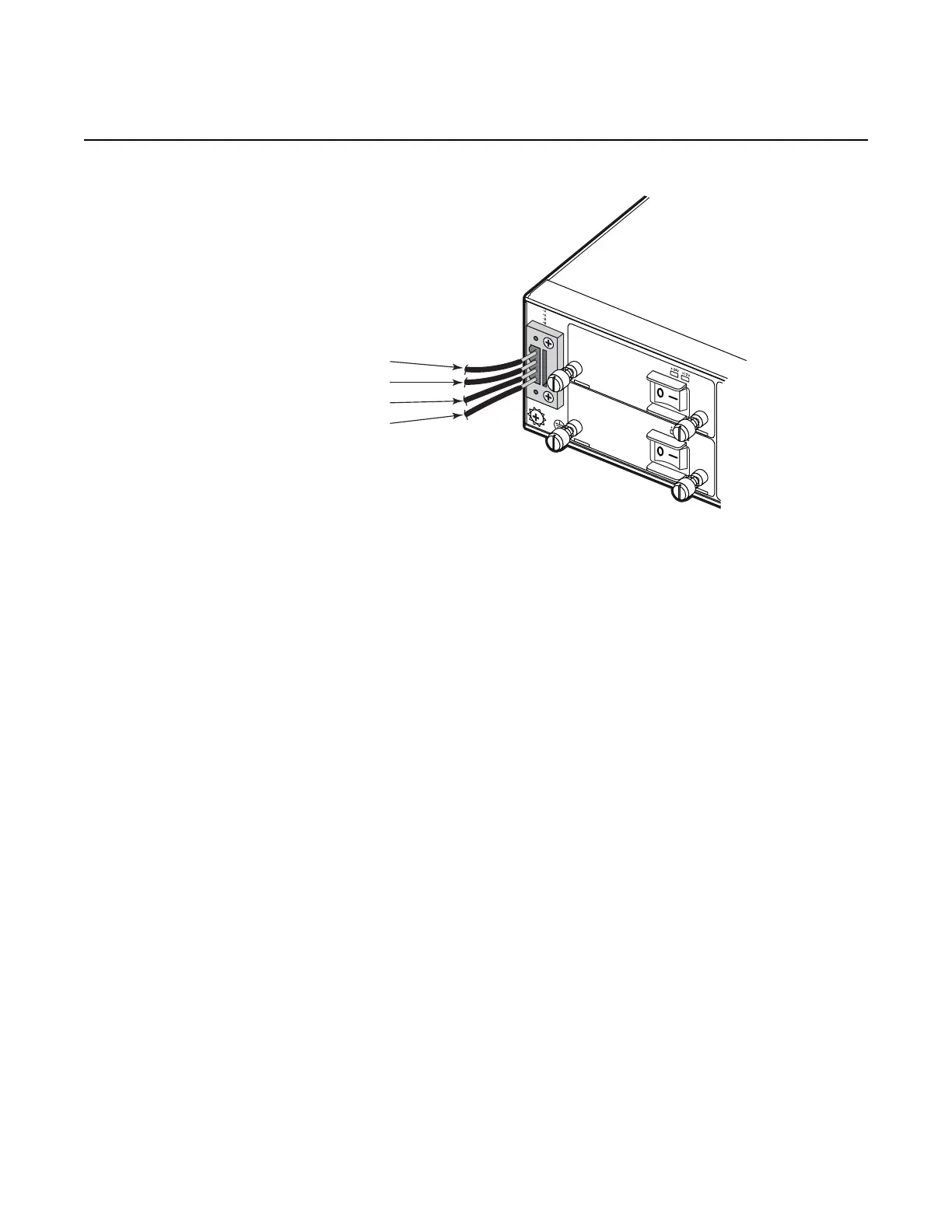
Figure 14 Connecting to a +24 VDC Power Source
Step 3. After the power source is turned on, switch the power button on the front of
the power module to the ON position (marked “—”).
Step 4. Check the LEDs on the power module as the switch is powered on to verify
that the –48V/+24V LED indicating external power status is on, and that the
+12V LED indicating internal power conversion is on. If not, recheck the
power cable connections at the power source and the power module.
Step 5. If you have installed both a primary and redundant power module, verify that
the LEDs on both modules are lit as indicated in step 4.
Ground (A) (Pin 1)
+24V (A) (Pin 2)
Ground (B) (Pin 1)
+24V (B) (Pin 2)
+24V
DC PEM
200W
+24V
DC PEM
200W
 Loading...