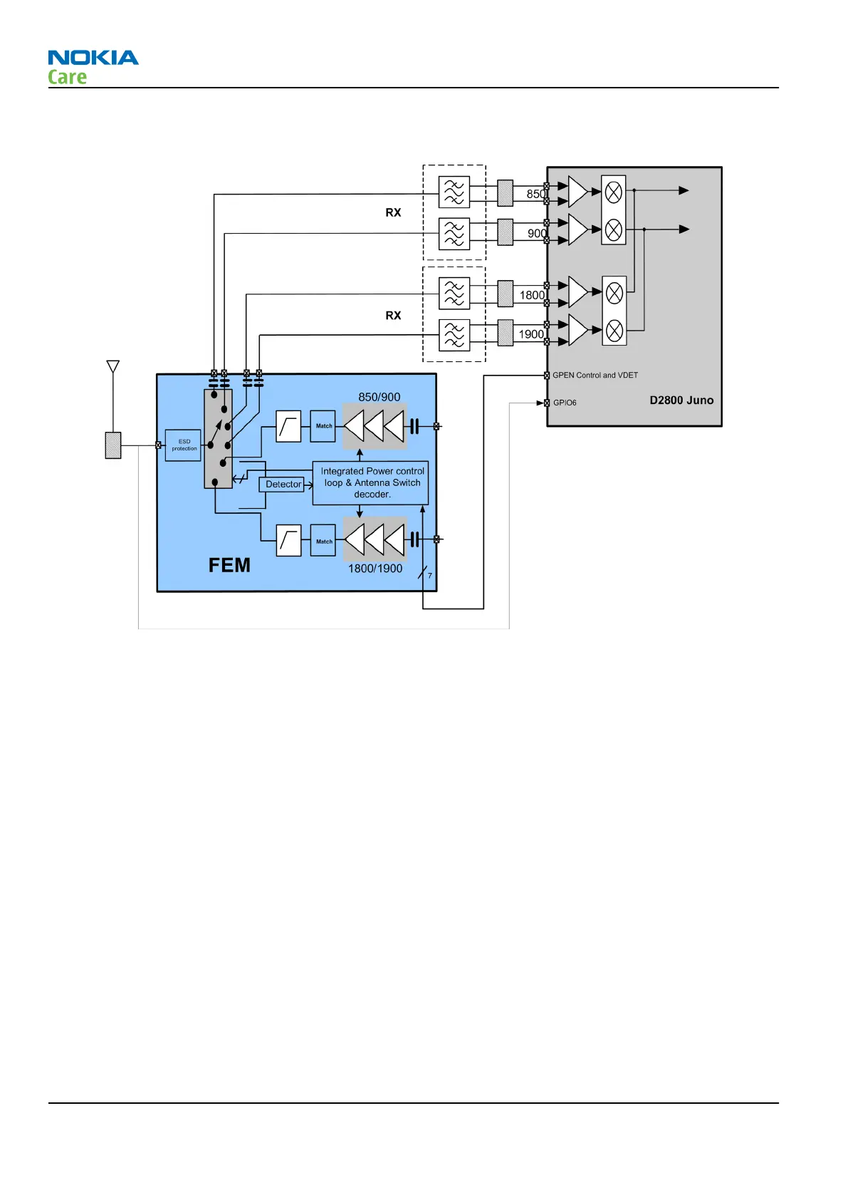
The following figure shows the interface between the receiver section of D2800 Juno’s integrated RF with
the FEM.
Figure 53 RF receiver module
Introduction to Receiver Functionality
The analogue signal is received by the phone’s antenna and is converted to a digital signal by the integrated
RF and processed by the D2800 Juno BB ASIC (i.e., to the earpiece).
Most of the receiver functions are integrated inside D2800 Juno BB ASIC. Signal with different frequencies
take different paths, therefore are handled by different components. The only required external components
are a single antenna switch a SAW filter, including matching, for each of the four frequency bands. The
antenna switch circuitry is a part of the Front End Module (FEM) and the four SAW filters (Z7500 & Z7501) are
contained in 2 dual packages where one is used for low bands (GSM850/GSM900) and the other for high bands
(GSM1800/GSM1900).
GSM Transmitter
The transmit chain consists of the transmitter section of the D2800 Juno’s integrated RF and a dual-mode
quad-band FEM.
RM-497
System Module
Page 5 – 42 COMPANY CONFIDENTIAL Issue 1
Copyright © 2010 Nokia. All rights reserved.