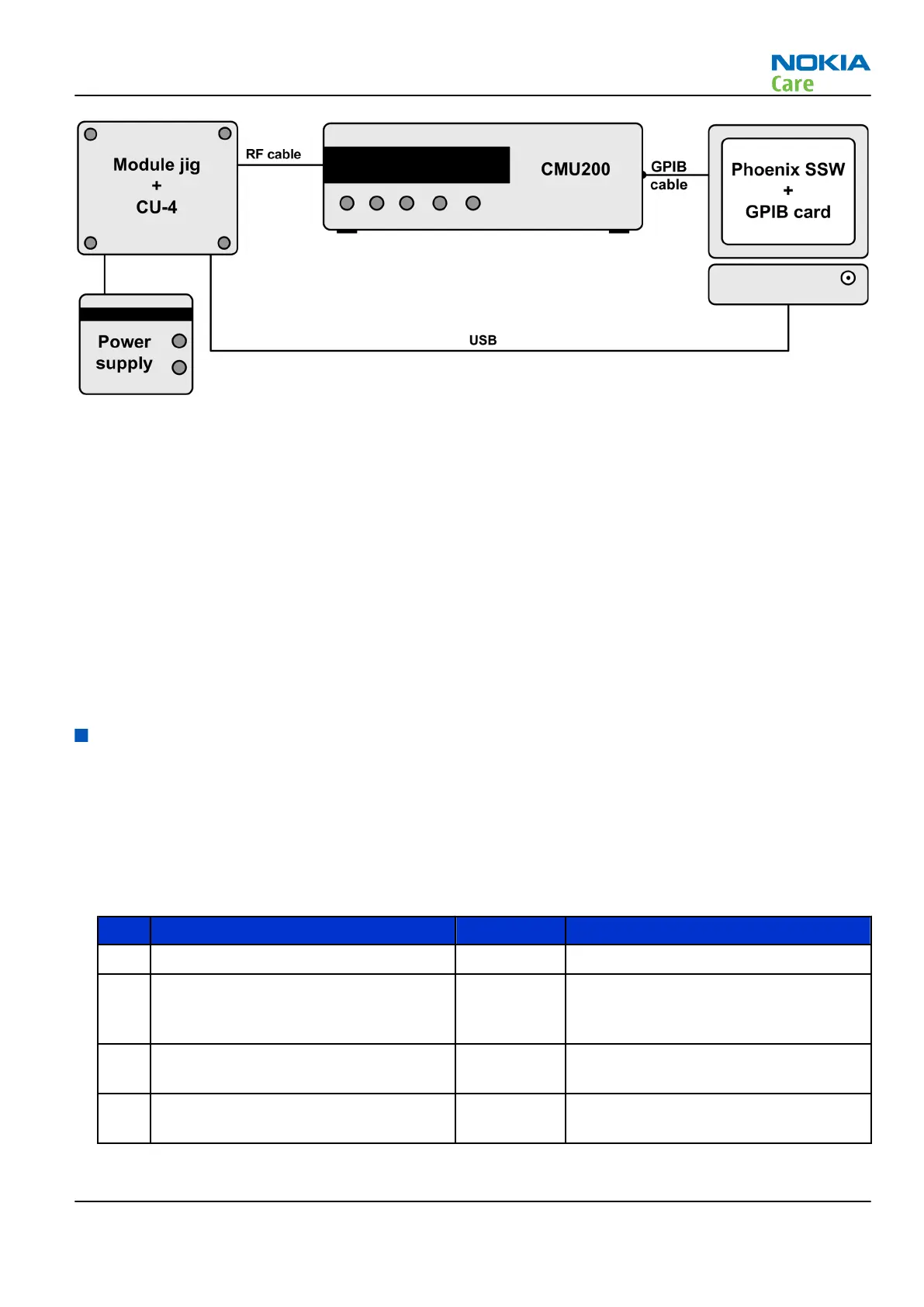
Figure 23 Auto tuning concept with CMU200
Note: Crossover Cable connection between computer and CMU200 is recommended (refer to Service
devices chapter and Module Jig concepts).
Phoenix and config file preparations
Install the phone specific data package. This defines phone specific settings.
Setup a new folder under
Phoenix -> Products
, rename it as RM-586, copy voyager_rf.xml to this folder.
Auto tuning procedure
1 Make sure the phone (in the jig) is connected to the equipment. Else, some menus will not be shown in
Phoenix.
2 To go to autotune, select
Tuning (Alt-U)
>
Auto-Tune (Alt-A)
from the menu.
3 Start autotuning, clicking the
Tune
button.
General RF voltage checking
General voltage checking
Steps
1. Set up the engine board in the module jig. The phone should be in local mode.
2. Check the following:
Table 2 21351/Juno Supplies
# Signal Name Test Point Voltage (All Bands)
1 VDCXO (INT_VDCXO) C2813 1.3V (analog supply for DCXO)
2 VRF1 (VRF1_RX, VRF1_PLL, VRF1_TXPLL) C2817 or
C2819 or
C2868
1.3V (analog supply for RX, Main PLL,
TXPLL)
3 VCORE (VCORE_DSP) C2822
(L2819)
1.2V (Digital Supply for DSP)
4 VRF2 C2810 or
C2866
2.7V (analog supply for RX & PA Driver
& LDO)
RM-497
RF troubleshooting
Issue 1 COMPANY CONFIDENTIAL Page 4 – 7
Copyright © 2010 Nokia. All rights reserved.