14
MA-100UniversalBaseInstallation
TheMA-100baseisdesignedprimarilyforreplacement
installation of the CMF95 series furnace where the
manufactured home duct system may be too small or
restrictiveforproperairow.TheMA-100baseprovides
approximately4inchesofadditionalplenumspacebefore
thedischargeairenterstheductsystem.SeeFigure10.
1.Usingtheuniversalbaseasaguide,locateandmark
the12-1/8”x12-1/8”openingfortheFeederDuct.
2.Cutall4sidesoftheFeederDuctopening1”largerthan
thedrawncutout.NOTE:Cuttingtheopeningto14-1/8”
x14-1/8”willallowthefourangesontheundersideof
thepaneltotintotheopening.
3.Drilla1”diameterholeforthegaslinethroughtheoor
andbottomboardtotheoutside.NOTE:Fuellinesare
notsuppliedwiththefurnace.Theyshouldbeinstalled
tocomplywithallapplicablecodes.
4.Settheuniversalbaseinplace.Droptransitionoroffset
feederduct(Figure8)upsidedownthroughtheoor
openingandcenterthetopofthefeederductin14-1/8”
x14-1/8”ooropening.
5.Usingthefeederductasaguide,markandcuta12”x
12”openinginthesupplyduct.Removethebaseand
transition feeder duct; then cut the opening into the
distributionduct.
6.Insert the feeder tabs into the main duct and bend
themoveruntilthemainductedgesaretrappedtightly
betweenangesandtabs.NOTE:Metaltapemaybe
usedtoensureanairtightconnection.
7.Setthe bottombasepaneloverthe feederduct. Slit
thecornersofthefeederductdowntothetopofthe
base.Whilethetopofthedistributionductispulledup
withonehand,benddowneachsideofthefeederduct
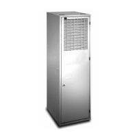
Figure10.MA-100UniversalBase,BottomPanel
12 1/8
Feeder Duct
Opening
18 1/4
24 1/2
12 1/8
FRONT
Combustion Air
Knock-outs
(7-1/4” X 2-1/4”)
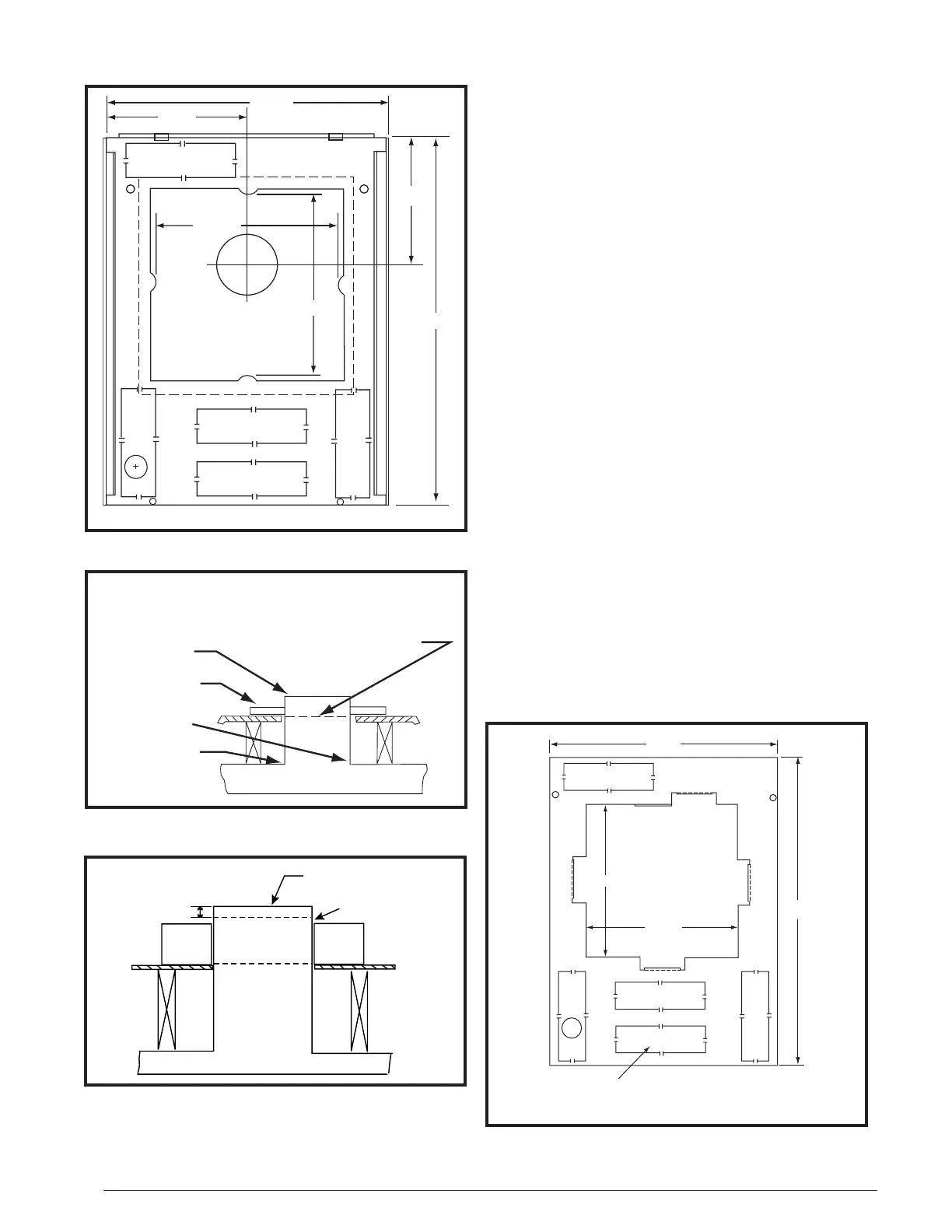
Figure7.MA-200BasePan
FRONT
Feeder Duct
Opening
Flue
Location
24 1/8
8 3/8
12 1/8
12 1/8
9 1/8
18 1/4
Figure 8. Transition Duct
Heater Duct Below Joists
Flange
Bend
Over Tabs
Base
Floor
Joists
Slit 4 Corners
Bend Down 4 Sides
TRANSITION
DUCT
Figure 9. Feeder Duct Installation
Heat Duct Below Joists
Base
Feeder Duct
Floor
Joists
Cut This Line
Bend Over
Along This Line
1"
 Loading...