8
• Thequalityofoutdoorairmustalsobeconsidered.Be
surethatthecombustionairintakeisnotlocatedneara
sourceofsolventfumesorotherchemicalswhichcan
cause corrosion of the furnace combustion system.
(Seepage5forasamplelistofsubstances).
• Routepipingasdirectaspossiblebetweenthefurnace
and the outdoors. Longer vent runs require larger
diameters.Ventpipingmustbeslopedupwards1/4”
perfootinthedirectionfromthefurnacetotheterminal.
Thisensuresthatanycondensateowsbacktothe
condensatedisposalsystem.
• When a Direct Vent (2-pipe) system is used, the
combustionairintakeandtheventexhaustmustbe
locatedinthesameatmosphericpressurezone.This
meansbothpipesmustexitthebuildingthroughthe
sameportionofexteriorwallorroofasshowninFigure
20,page33.
• Piping must be mechanically supported so that its
weightdoesnotbearonthefurnace.Pipe supports
mustbeinstalledaminimumofevery5feetalongthe
ventruntoensurenodisplacementafterinstallation.
Supportsmaybeatshorterintervalsifnecessaryto
ensurethattherearenosaggingsectionsthatcantrap
condensate. It is recommended to install couplings
alongtheventpipe,oneithersideoftheexteriorwall
(Figure20).Thesecouplingsmayberequiredbylocal
code.
• Ifbreakableconnectionsarerequiredinthecombustion
airinletpipe(ifpresent)andexhaustventpiping,then
straight neoprene couplings for 2” or 3” piping with
hose clamps can be used.These couplings can be
orderedthroughyourlocalfurnacedistributor.Toinstall
acoupling:
1. Slidetherubbercouplingovertheendofthepipe
thatisattachedtothefurnaceandsecureitwith
oneofthehoseclamps.
2. Slidetheotherendoftherubbercouplingontothe
otherpipefromthevent.
3. Securethecouplingwiththesecondhoseclamp,
ensuringthattheconnectionistightandleakfree.
OutdoorTerminations-HorizontalVenting
• Ventandcombustionairintaketerminationsshallbe
installedasshowninFigures1&2(page9)andin
accordancewiththeseinstructions:
• Ventterminationclearancesmustbeconsistentwiththe
NFGC,ANSI2223.1/NFPA54and/ortheCSAB149.1,
NaturalGasandPropaneInstallationCode.Table12
(page32)liststhenecessarydistancesfromthevent
terminationtowindowsandbuildingairintakes.
• Vent and combustion air intake terminations must
be located to ensure proper furnace operation and
conformance to applicable codes. A vent terminal
mustbelocatedatleast3feetaboveanyforcedair
inletlocatedwithin10feet.Thisdoesnotapplytothe
combustionairinletofadirectvent(twopipe)appliance.
InCanada,CSAB149.1takesprecedenceoverthese
instructions.SeeTable12(page32).
totallength,includingtheequivalentttinglengths,must
belessthanthemaximumlengthspeciedinthetable.
Condensingfurnacecombustionproductshaveverylittle
buoyancy,soTable2istobeusedwithoutconsideration
ofanyverticalriseinthepiping.
VentPipeMaterial
Ventandcombustionairpipeandttingsmustbeoneof
thefollowingmaterialsinthelistandmustconformtothe
indicatedANSI/ASTMstandards.Cementmustconform
toASTMStandardD2564forPVCandStandardD2235
forABS.PVCprimermustmeetstandardASTMF656.
WhenjoiningPVCpipingtoABS,usePVCsolventcement.
(SeeprocedurespeciedinASTMStandardD3138).
In Canada, all plastic vent pipes and ttings including
anycement,cleaners,orprimersmustbecertiedasa
systemtoULCS636.Howeverthisrequirementdoesnot
applytopipinginternaltothefurnace.
Materials Standards
SCHEDULE40PVC............................................... D1785
PVC-DWV.............................................................. D2665
SDR-21&SDR-26................................................. D2241
ABS-DWV.............................................................. D2661
SCHEDULE40ABS.............................................. F628
FOAM/CELLULARCOREPVC........................... F891
VentPipeInstallation
CAUTION:
Combustion air must not be drawn from a
corrosiveatmosphere.
Thisfurnacehasbeencertiedforinstallationwithzero
clearancebetweenventpipingandcombustiblesurfaces.
However,itisgoodpracticetoallowspaceforconvenience
ininstallationandservice.
• In the absence of local codes, the location of any
combustionairinletrelativetoanyventterminalmust
beatleast8inches.Thisincludesinstallationsinvolving
morethanonefurnace.
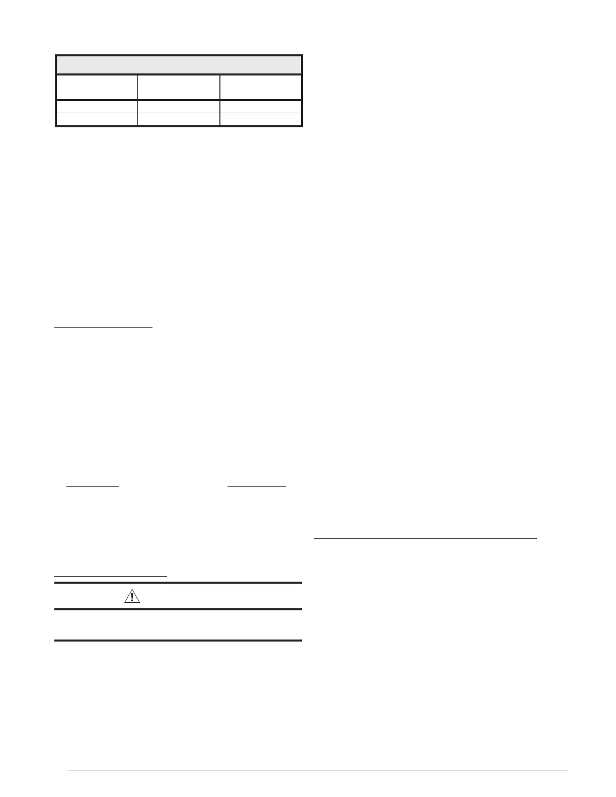
MaximumDirectVent,DualPipeLength(FT.)
CMF95 INPUTS
(BTU)
INLET / OUTLET
2” Diameter
INLET / OUTLET
3” Diameter
45,000 30 60
72,000 30 60
†
NOTES:
1. Subtract2.5ft.foreachadditional2inchlongradiuselbow,subtract
5ftforeachadditional2”shortradiiouselbow,subtract3.5ft.for
eachadditional3inchlongradiuselbow,and7ft.foreachadditional
3inchshortradiuselbow.
2. Two45degreeelbowsareequivalenttoone90degreeelbow.
3. Thistableappliesforelevationsfromsealevelto2,000ft.Forhigher
elevations,decreasepipelengthsby8%per1,000ftofaltitude.
Table2.VentPipeLengths
 Loading...