22
HeatAnticipator
Set the heat anticipator according to the instructions
suppliedbythethermostatmanufacturer.Todetermine
theheatanticipatorsetting:
1.Addthecurrentdrawofthesystemcomponents;or
2.MeasurethecurrentowonthethermostatR-Wcircuit
afterthecirculatingblowermotorhasstarted.
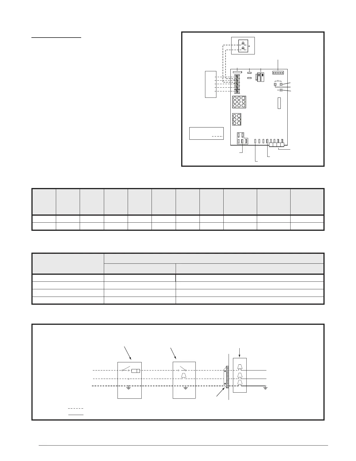
Figure 16. Line Voltage Field Wiring
Field Supplied
Disconnect w/in
Sight of Furnace
Field Supplied
Panel Connector
Field Supplied
Fused Service
Panel
Black (Hot)
White (Neutral)
Green or Bare
(Ground)
Black
White
Black
White
Black
White
Field Line Voltage Wiring
Factory Line Voltage Wiring
Ground
Ground
Junction Box (may be int. or ext. to the furnace). These
connections can be made in the field supplied disconnect
at the furnace. NOTE: Connections made within the furnace
burner compartment do not require a junction box.
Ground
Furnace
Model
Number
CMF95-
Furnace
Input
(Btuh)
Cabinet
Width
(in.)
Nominal
Electrical
Supply
Maximum
Operating
Voltage
Minimum
Operating
Voltage
Maximum
Furnace
Amperes
Minimum
Wire
Gauge
Maximum
Fuse or Circuit
BreakerAmps*
Minimum
Circuit
Ampacity
1
Mamimum
Overcurrent
Protection
2
045 45,000 18 115-60-1 127 103 11.0 14 20 13.1 21.7
072 72,000 18 115-60-1 127 103 10.4 14 20 12.4 20.4
NOTE:Minimumwiregaugeandmaximumfuse/circuitbreakeramperagearebasedonMCA
1
andMOP
2
calculations.Thisfurnaceis
approvedforinstallationwitha15or20ampfuse/circuitbreakerhoweverwiringsizingmustadheretocurrentversionoftheNECand/or
applicablelocalcodesdependingupontheovercurrentprotection.
ThermostatWireGauge
RecommendedThermostatWireLength
2-wire-Heating 4or5wire-Cooling
24 55ft. 25ft.
22 90ft. 45ft.
20 140ft. 70ft.
18 225ft. 110ft.
* Time-delayfusesorcircuitbreakersarerequired.
Table4.WireLength&VoltageSpecications
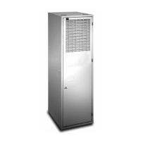
Figure15.LowVoltageField,Four-wire
Heating/CoolingApplications
RCYGW
STATUS
FLAME
GREEN
RED
180
COOL
HEAT
120
90
60
YELLOW
BLOWER
OFF
DELAY
LOW
ML
MH
HIGH
EAC
L1
XFMR
HUM
COM
SPEED
SELECT
3 AMP
FUSE
24V
5
NEUTRALS
ROOM
THERMOSTAT
A/C CONDENSING UNIT
CONDENSING UNIT
CONTROL BOX
EXPANSION PORT
(MOTOR CONNECTION)
FIELD WIRING
LOW VOLTAGE
CONNECTION
R
C
Y
G
W
NOTE: The “Y” terminal
on the control board
must be connected to the
thermostat for proper
cooling mode operation.
Connect
R & W
For Heating
Only
2
ELECTRONIC AIR CLEANER
MOTOR SPEED TAPS
(NOT USED)
HUMIDIFIER TA P
NEUTRAL LEADS
6 3
4
1
7
8
9
5
2
63
4
1
FAN
 Loading...