27
Ifthefurnacefailstooperatecheckthefollowing:
• Isthethermostatoperatingproperly?
• Aretheblowercompartmentdoor(s)inplace?
• Isthefurnacedisconnectclosed?
• Hasthecircuitbreakertrippedorthecontrolboardfuse
burnedopen?
• Isthegasturnedon?
• Areanymanualresetswitchesopen?
• Isthelterdirtyorplugged?
• Istheamesensorcoated?(Removeandcleanwith
steelwool.(Donotuseemeryclothorsandpaper!)
• Isthereblockageinthecondensatedrainswitch?Also
verifythatthereisnodoubletrappingofcondensate.
• Isthe secondaryheatexchangerfreeofdebrisand
clogs?
• Isevaporatorcoilcleanandfreeofdebris(Ifapplicable).
• ArealltheLED’sonthefurnacecontrolboardconstantly
ON?Ifnot,refertoTable6orthewiringdiagram(Figure
18,page29)todeterminefaultcondition.
IMPORTANTNOTE:Thefurnacewilllockoutafter5
failedattemptsforignitionandwilltryagainevery
hourifthecallforheatremains.
• Iftheinducerblowerisoperating,anditemsabovehave
beenveried,checktheblowerlimitswitchandreset
ifnecessary.SeeFigure17forcomponentlocation.
• IfthefurnaceoperateswhentheBlowerLimitSwitchis
reset,contactaqualiedservicetechniciantoidentify
andrepairtheproblem.
• If the furnace still doesn’t operate,check the ame
roll-outswitch(Figure17)andresetifnecessary.
• Ifthefurnaceoperateswhentheamerolloutswitchis
reset,contactaqualiedservicetechniciantoidentify
andrepairtheproblem.
DiagnosticDescription Green LED Red LED
ControlFault(NoPower) Off Off
L1/NeutralPolarityFault Flash Flash
1HourLockout AlternatingFlash
NormalOperation On On
PressureSwitchClosedFault On Flash
PressureSwitchOpenFault Flash On
OpenLimitSwitchFault Flash Off
MotorFault On Off
DiagnosticDescription Yellow LED
LowFlameSensorSignal ContinuousFlash
FlamePresent On
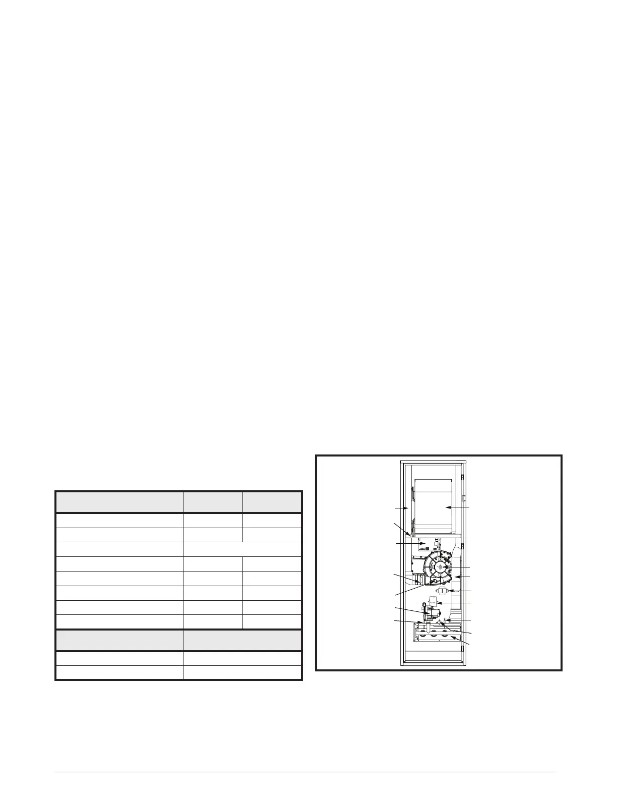
Table 6. Control Board Fault Conditions
TROUBLESHOOTING DESCRIPTION OF COMPONENTS
Thedescriptionsbelowarevariousfunctionalcomponents
thataffecttheoperationandshuttingdownofthisfurnace.
Someofthesecomponentsandtheirlocationsareshown
inFigure17.Ifanycomponentofthefurnacemustbe
replaced,useonlyfactoryauthorizedreplacementparts
speciedintheReplacementPartsListprovidedonline.
BlowerLimitSwitch:Preventsoperationwhenblower
isnotoperational.
Flame Sensor: Verieswhenaamehascarriedover
fromtheignitertotheoppositeendburner.Ifnoameis
detected,thefurnacewillshutdownwithin4seconds.
FlameRoll-OutSwitch:Veriesthattheburnerames
aredrawnintotheheatexchangertubes.Iftheburner
amesarenotproperlydrawnintotheheatexchanger,the
ameroll-outswitchwillclosethegasvalveandinitiate
theshutdowncycle.
GasValve:Controlstheowofgastotheburners.When
the gas valve is energized it automatically opens and
regulatesthegaspressureinthemanifold.
Inducer Assembly: Vents products of combustion to
theoutside.
Pressure Switch:Veries that the inducer is drawing
thecombustiongasesthroughtheheatexchanger.The
pressureswitchpreventsfurnaceoperationwithexcessive
ue/condensateblockageorimproperinduceroperation.
Main Air Limit Switch: Prevents the air temperature
leavingthefurnacefromexceedingthemaximumallowable
outletairtemperature.
Figure17.FurnaceComponents
Blower Assembly
Inducer Assembly
Gas Valve
Gas Manifold &
Burner Assembly
ON / OFF Switch
Control Board
Limit Switch
Inline Drain
Assembly
24V Transformer
Igniter
Main Air Limit Switch
Flame Sensor
Roll-Out Switch
Combustion Air Pipe
Exhaust Vent Pipe
 Loading...