9
• Allminimumclearances(Figure2)mustbemaintained
toprotectbuildingmaterialsfromdegradationbyue
gases.
• For optimal performance, vent the furnace through
awallthatexperiencestheleast exposuretowinter
winds.
• The vent termination shall be located at least 3 ft.
horizontallyfromanyelectricmeter,gasmeter,regulator
andanyreliefequipment.ThesedistancesapplyONLY
to U.S. installations. In Canada, CSA B149.1 takes
precedenceovertheseinstructions.
• Donotinstalltheventterminalsuchthatexhaustis
directed into window wells, stairwells, under decks
orintoalcovesorsimilarrecessedareas,anddonot
terminateaboveanypublicwalkways.
• Ifventinghorizontally,sidewallventkitsareavailable
accordingtothepipediametersizeoftheinstallation.
For3inchpipeusekit#904347.Faceplatekit#902375
isalsoavailablefor3inchhorizontalventing.Please
followtheinstructionsprovidedwiththekits.
• Concentricventterminationkitsareavailableforuse
withthesefurnaces.For3inchpipeusekit#904953.
Pleasefollowtheinstructionsprovidedwiththekit.
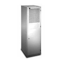
• Whentheventpipemustexitanexteriorwallcloseto
thegradeorexpectedsnowlevelwhereitisnotpossible
toobtainclearancesshowninFigure1,arisermaybe
providedasshowninFigure3.Insulationisrequired
topreventfreezingofthissectionofpipe.SeeTable3
(page10)forventfreezingprotection.
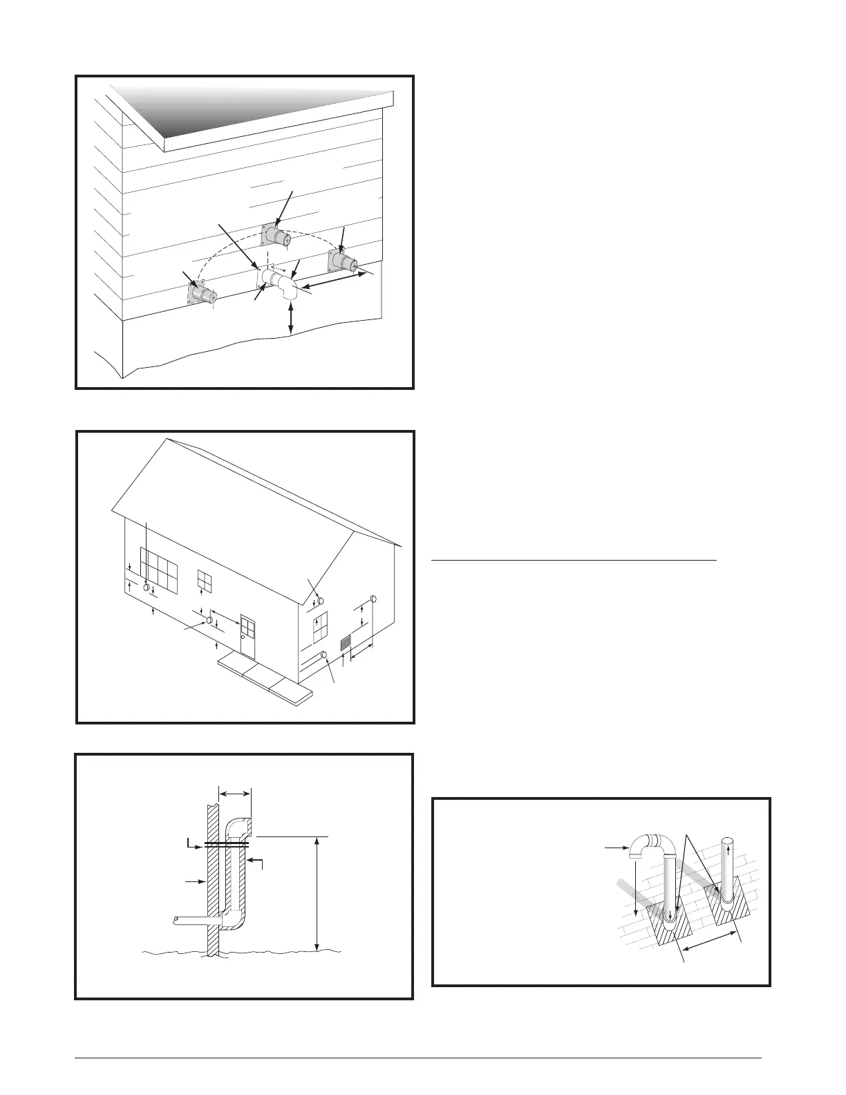
OutdoorTerminations-VerticalVenting
Terminationspacingrequirementsfromtheroofandfrom
eachotherareshowninFigure4.Theroofpenetration
mustbeproperlyashedandwaterproofedwithaplumbing
roofbootorequivalentashing.Ventandcombustionair
pipingmaybeinstalledinanexistingchimneywhichis
notinuseprovidedthat:
• Boththeexhaustventandairintakerunthelengthof
thechimney.
• Thetopofthechimneyissealedandweatherproofed.
• The termination clearances shown in Figure 4 are
maintained.
• Noothergasredorfuel-burningequipmentisvented
throughthechimney.
12” min. to maximum
expected snow level
(both pipes)
90° Elbow
Exhaust vent
option B
Exhaust vent
option A
Mounting kit faceplate
secured to wall with screws
(both pipes)
Combustion
air inlet
Exhaust vent
option C
18” Min.
36” Max.
8” Min.
36” Max.
(all positions)
Figure1.Inlet&ExhaustPipeClearances
Note 2
Mechanical draft
vent terminal
Direct vent
terminal
50,000 Btuh
or less
Forced air inlet
Direct vent
terminal - more
than 50,000 Btuh
Mechanical
draft vent
terminal
Mechanical
draft vent
terminal
Less
than
10 ft.
3 ft.
NOTES:
1. All dimensions shown are
minimum requirements.
2. Exterior vent terminations must
be located at least 12” above the
maximum expected snow level.
Note 2
4 ft
4 ft
12 in.
12 in.
9 in.
Note 2
Figure 2. Vent Locations
Support
NOTE: Vent Configuration to Provide
12" Minimum height above Snow Level.
1/2"
Armaflex
Insulation or
Equivalent
(if required)
12" Above
Maximum
Expected
Snow Level
19" Max.
(See Note)
Outside
Wall
Figure 3. Alternate Horizontal Vent Installation
Figure4.VerticalVentTermination
Combustion Air
Exhaust Vent
12” Above Maximum
Expected Snow Level
(Both pipes)
Elbows on the combustion air
inlet must be positioned pointing
away from the exhaust vent.
8" Min.
36" Max.
Plumbing Vent Roof Boot
(Both Pipes)
 Loading...