15
tightlytothebasewiththeotherhand.Trimthemetal
toallowoneinchangeoverthetopofthebaseand
sealthatangewithmetaltape.
8.Securethetoppaneltotheoorwith2screwsthrough
thefrontange.NOTE:Ifusinga“V”or“U”-boxcrossover
system,usemanufacturersinstructionsforinstallation
details.
InstallingtheFurnaceonanMA-100Base
1.Carefullyliftthefurnaceovertheuniversalbasepan
andsetintoposition.Avoiddamagingthefeederduct
assembly.NOTE: Makesurethefurnaceispositioned
againstthebackendofthebase.
2.Openthefurnacedoorandfastenthefurnacetothe
baseusing#8x1/2”sheetmetalscrews.
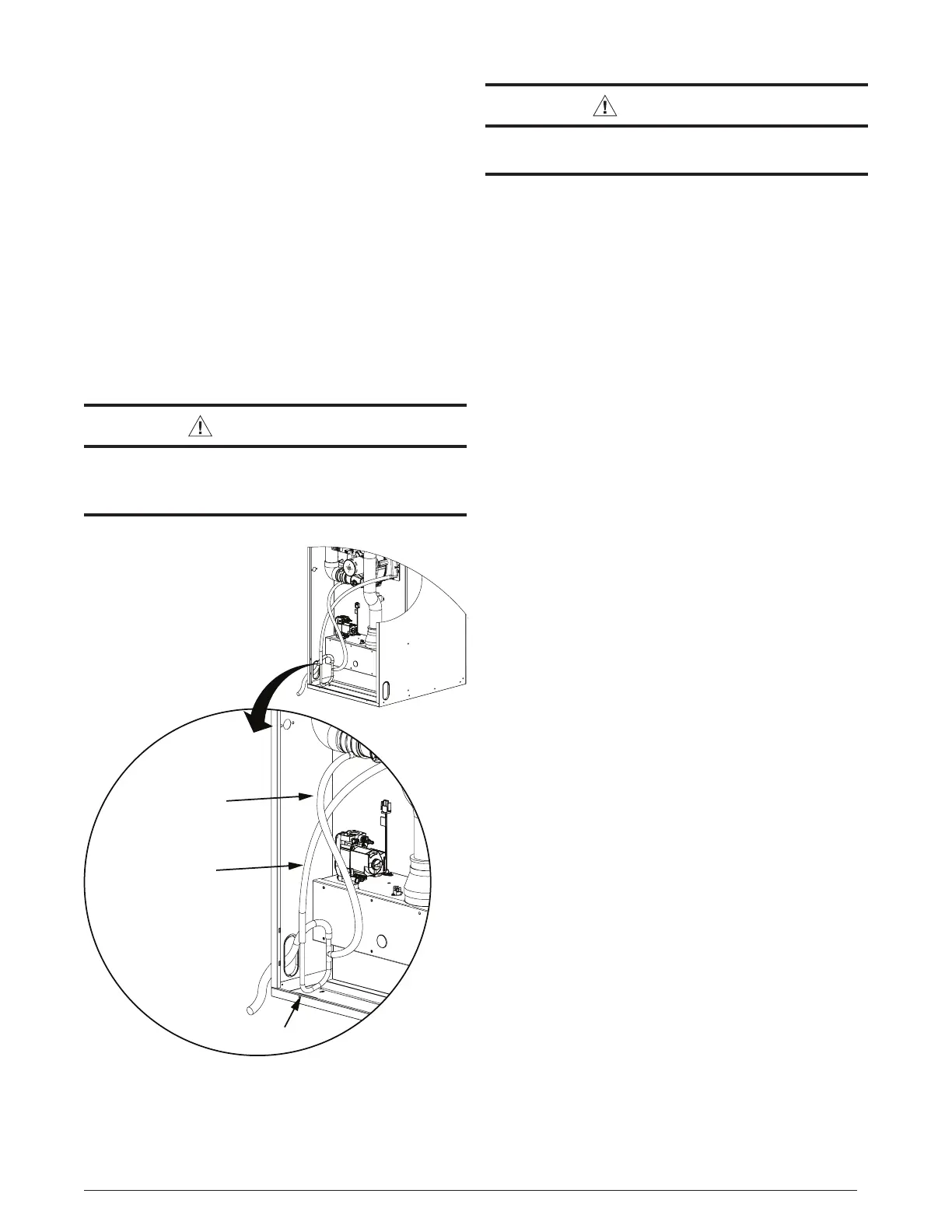
Condensate Drainage
WARNING:
Thecondensateproducedbythefurnacemust
bedrained.Donotconnectawatersupplyto
thedrainagehoseofthefurnace.
Figure 11. Condensate Drainage
J-Trap
Drain Pipe Routed
thru Slot in Cabinet
To External Drain
Inline Drain
Assembly
Collector
Box Drain
Collector
Box Drain
CAUTION:
Donotinstalladditionaltrapsinthecondensate
drain.
• If the furnace is installed in an area where
temperaturesfallbelowfreezing,specialprecautions
mustbemadeforinsulatingcondensatedrainlines
thatdraintotheoutdoors.Ifcondensatefreezes
inthelines,thiswillcauseimproperoperationor
damage to the furnace. It is recommended that
alldrainlinesontheoutsideoftheresidencebe
wrappedwithanindustryapprovedinsulationor
materialallowedbylocalcode.
• Beforeroutingthedraintubeoutofthefurnace,loosen
thetubeclampandturnthetubesothepreset90°turn
facestheintendeddirectionofexitfromthecabinet.Do
notroutethedraintubewithoutrotatingthetuberst.
Thiswillkinkthetubeandpreventcondensatefrom
draining.
• Careshouldbetakentoroutethedrainlineawayfrom
theburnerbox.Drainlinesrestingontheburnerbox
canbecomekinkedorcollapsedduetotheheatfrom
theburnerbox.
• Thecondensatedrainmayexitthroughtheleftorright
slotsinthebottomofthefurnace(Figure11).Makesure
theexibledrainhoseisnotkinked.
• Thecondensateshoulddrainfromtheplasticcollector
boxas droplets or a small stream.If younotice the
furnacehasoperatedformorethan5minuteswithout
drainingorthestatuslightsonthecontrolboardindicates
anopenpressureswitch(Table6,page27)followthe
stepsbelow.
1.Removethecollectorboxsofttube(Figure11)and
verifytheexitfromthecollectorboxisclearofany
debrisorobstructions.
2.Replacethistubeandverifythettotheheaderspout
isairtight.Airwillbedrawnintotheheaderifthis
connectionisnottight.
3.Checkothertubeconnectionsalongthedrainsystem.
Verifythatallareairtight.
 Loading...