System Components System Overview
NFS-640 Installation Manual P/N 51332:B1 12/01/2003 13
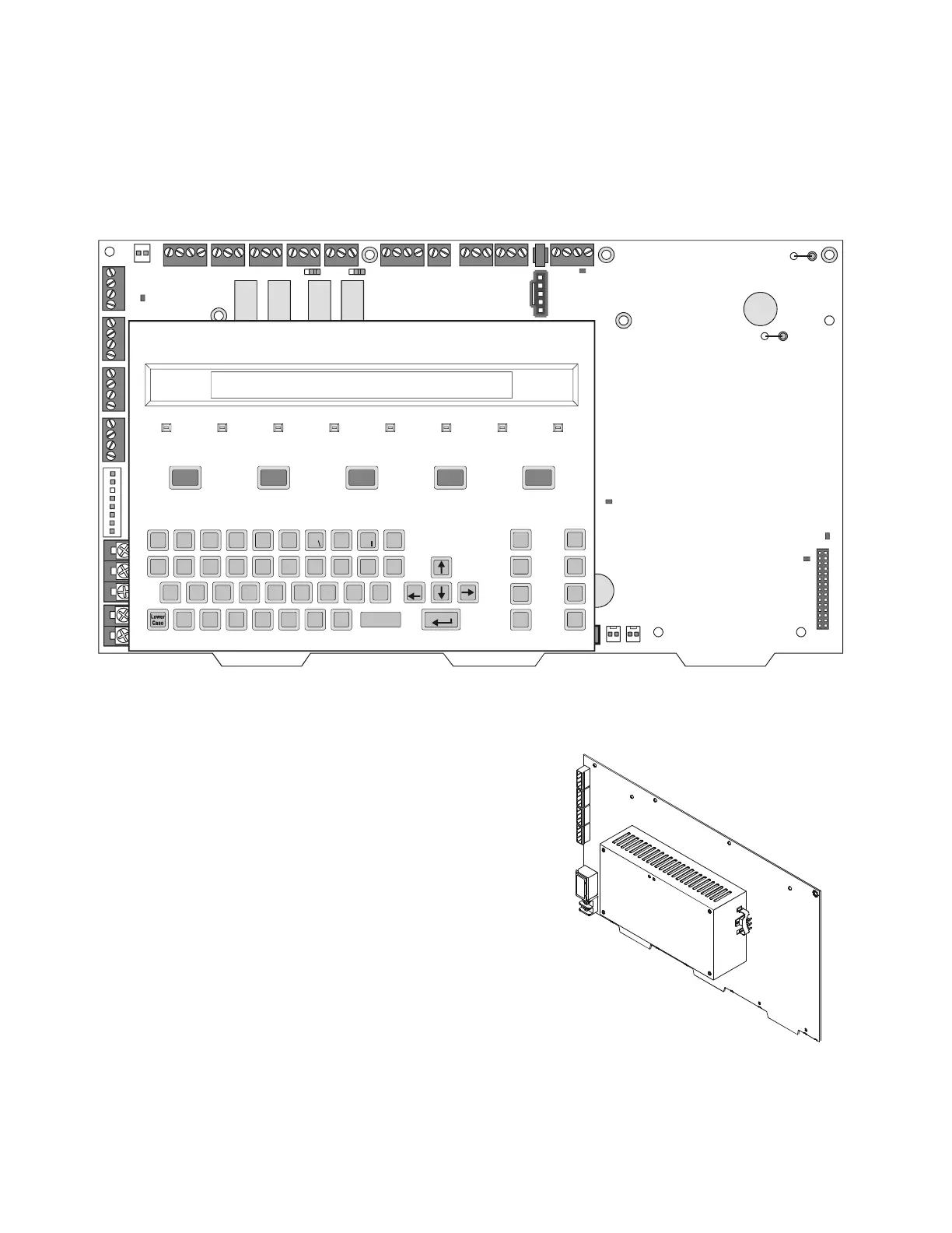
2.2.2 Control Panel Circuit Board
The control panel electronics are contained on one four-layer printed circuit board (PCB) that
incorporates a 6 amp power supply with battery charger, a signaling line circuit (SLC) and the
central processing unit. A keypad/display unit can be installed over the power supply as shown
Figure 1.
Figure 1 NFS-640 Control Panel with Optional Keypad/Display Unit Installed
2.2.3 Main Power Supply
The main power supply is an integral part of the
control panel’s circuit board. It provides a total of
3 A (6 A in alarm) and contains an integral battery
charger. This can be used for many functions
including:
• Powering the NFS-640
• Powering a variety of UL-listed 24 VDC
notification appliances from four built-in
NAC outputs
• Providing up to 1.25 A of resettable power
for four-wire smoke detectors
• Providing up to 1.25 A of non-resettable
power for external devices such as the TM-4
Transmitter Module.
Z X C V B N M
A S D F G H J K L
Q W E R T Y U I O P
*
#
&
/
+
–
(
)
1234567890
!
@
=
,
%: .
?
NEXT
SELECTION
PREVIOUS
SELECTION
DETECTOR
MODULE
OUTPUT
RECALL
LAST
ENTRY
INCRE MENT
NUMBER
BATTERY
LEVELS
SPACE
FIRE
ALARM
ACKNOWLEDGE
SCROLL DISPLAY
SIGNAL
SILENCE
PRE-ALARM SECURITY SUPERVISORY SYSTEM
TROUBLE
POINT
DISABLED
SIGNALS
SILENCED
POWER
DRILL
HOLD 2 SECONDS
SYSTEM
RESET
LAMP
TEST
Esc
Enter
nfs640-panel.cdr
Figure 2 Main Power Supply on
Control Panel
nfs-640-panel-iso.cdr

 Loading...


