Installing Panel Circuit Modules Installation
NFS-640 Installation Manual P/N 51332:B1 12/01/2003 47
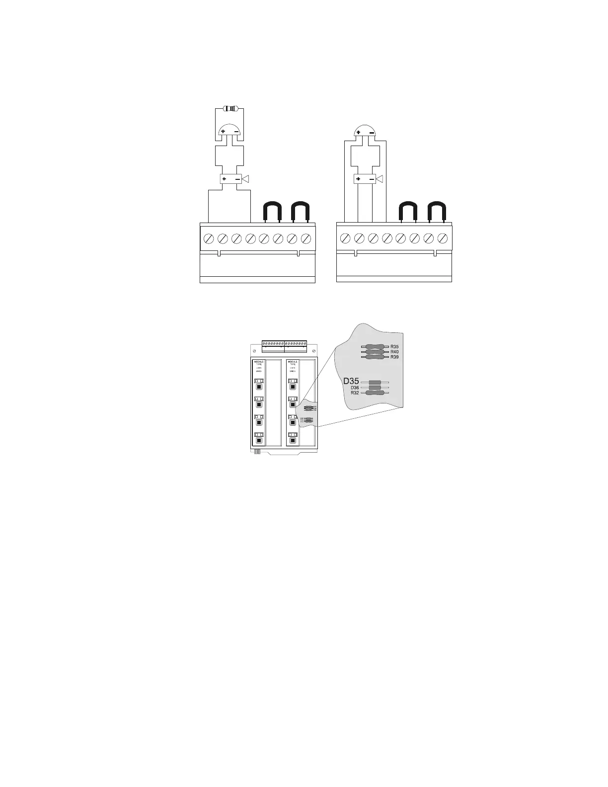
Figure 26 Field-Wiring an ICM-4RK/ICE-4
Figure 27 Location of D35 on ICM-4RK Circuit Board
3.7.7 Connecting CRM-4RK/CRE-4 Modules
Guidelines for field-wiring the CRM-4RK and the CRE-4:
• Provide Form-C relay contacts (silver alloy) used for medium duty switching or pilot duty.
• Terminals will accept wire sizes from 12 AWG to 18 AWG (3.1 to 0.78 mm
2
).
• Activation of a module or expander relay occurs automatically when an alarm is detected on
a programmed IDC.
• UL contact ratings are 5 A at 125 VAC (resistive) or 30 VDC (resistive) and 2 A at 125 VAC
(inductive).
• For more information, refer to Section 3.6 “UL Power-limited Wiring Requirements”.
• For typical field-wiring connections, refer to Figure 28.
B+ A+ A– B– B+ A+ A– B– B+ A+ A– B– B+ A+ A– B–
Jumpers for
unused circuits
4.7K,
1/2 watt ELR
P/N 71252
UL-listed 24 VDC
Polarized Devices
ICM4wire-YB.cdr
Typical NFPA
Style Z (Class A) NAC
Typical NFPA
Style Y (Class B) NAC
Jumpers for
unused circuits
Cut D35 on the circuit board to
produce California code.
icm-4rk-d35.cdr

 Loading...


