Applications Fire/Security Applications
60 NFS-640 Installation Manual P/N 51332:B1 12/01/2003
For bypass of security zones, use the DISABLE routine (covered in the Status Change section of
the NFS-640 Operations Manual) for Security type devices.
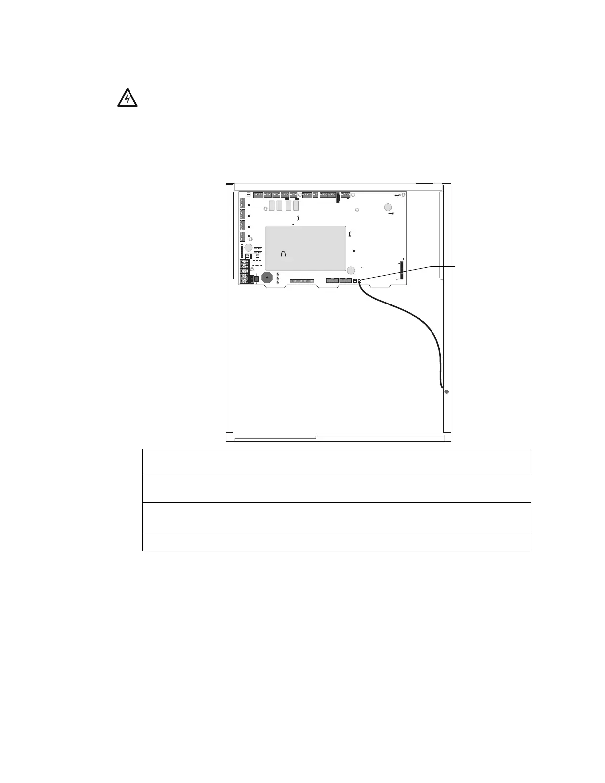
4.4.2 Installing a Security Tamper Switch
Follow the instructions below to wire the cabinet with a Security Tamper Switch kit model STS-1.
Figure 37 Installing the STS-1 Security Tamper Switch
4.4.3 Receiving Unit
For applications requiring transmission of security alarm information to a central receiving unit, the
control panel may be connected via a UDACT to a compatible receiving unit (see the UDACT
Manual). For information on configuring the Receiving unit for Combination Fire/Security
applications, refer to the documentation for that control panel.
!
WARNING: Damage can result from incorrect wiring connections.
nfs640-sts1.cdr
STS-1 mounting location
(side opposite of door hinges)
Connect to
J10 “Tamper”
Step Action
1 Install the STS-1 Tamper Switch onto the side of the backbox opposite the door hinge,
pushing the switch through the opening until it snaps into place.
2 Install the magnet on the same side of the cabinet door as the lock. Push the magnet
through the opening in the door until it snaps into place.
3 Connect the STS-1 connector to J10 (Tamper) on the Control Panel.

 Loading...


