Applications Releasing Applications
64 NFS-640 Installation Manual P/N 51332:B1 12/01/2003
4.5.3 Wiring
References to wiring diagrams for releasing applications:
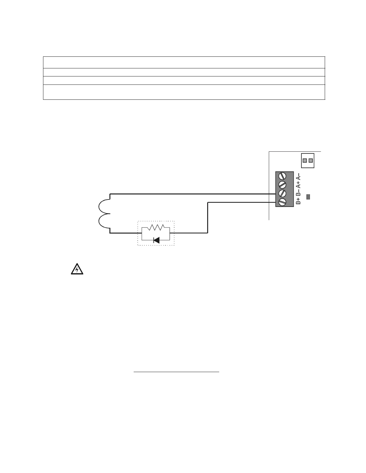
4.5.4 Connecting a Releasing Device to the Control Panel
Use TB3 (NAC#4), TB4 (NAC#3), TB5 (NAC#2), or TB6 (NAC#1) on the control panel for
NAC⁄Releasing Circuits. Only one releasing device can be installed per NAC.
Figure 39 Typical Style 4 Connection of a Releasing Device to Control Panel
Circuit Requirements. When connecting a releasing device, note the following:
1. The control panel provides four NAC/Releasing Circuits (Style Y or Z). Each circuit can
provide 2.5 A. Total current drawn from the power supply cannot exceed 6 A in an alarm
condition (refer to Table 12, “System Draw Current Calculations,” on page 71). Use UL-listed
24 VDC appliances only.
2. Circuits are supervised and power-limited (except if configured according to Note 4a below).
For more information, refer to the Device Compatibility Document.
3. For NFPA 13 and 15 applications, disable the Soak Timer (Soak=0000); for NFPA 16
applications, set the Soak Timer (0600-0900 seconds). Refer to the NFS-640 Programming
Manual for instructions on setting the Soak Timer.
4. In applications not requiring power-limited circuits
–
a) If the application does not require supervising the releasing device against shorts, End-of-
Line devices (P/N REL-2.2K) are not required;
b) Limited energy cable cannot be used for wiring of a releasing device circuit;
c) Maintain a 0.25 inch (6.35 mm) spacing between the releasing circuit device wiring and any
power-limited circuit wiring; and
d) Program the releasing circuit for Type Code
RELEASE CKT.
5. The releasing circuit must be programmed with a releasing type code listed in the NFS-640
Programming Manual.
To connect Refer to
A releasing device to the control panel. Section 4.5.4 “Connecting a Releasing Device to the Control Panel”.
A releasing device to the FCM-1 Module. Section 4.5.5 “Connecting a Releasing Device to the FCM-1 Module”.
An NBG-12LRA Agent Release-Abort
Station.
Section 4.5.6 “Connecting an NBG-12LRA Agent Release-Abort
Station”.
!
WARNING: Do not enable the BACKUP option switch for any of the four Notification Appliance
Circuits (NACs) if they are used for releasing functions!
+
–
nfs640-relconn1.cdr
REL-2.2K
Compatible UL-listed
24 VDC releasing device
B+ NAC/Releasing output (source)
B– NAC/Releasing output (source)
A+ Class A (return for NAC only)
A– Class A (return for NAC only)
Note: See text below for circuit requirements.

 Loading...


