Installing Panel Circuit Modules Installation
NFS-640 Installation Manual P/N 51332:B1 12/01/2003 45
3.7.5 Connecting ICM-4RK and ICE-4 Modules
The total current available for any group of Notification Appliance Circuits (NACs), other than the
four NACs on the control panel, cannot exceed the following:
• 6.0 A when powered from the APS-6R
• 1.25 A when powered from a NFS-640 DC power output terminal
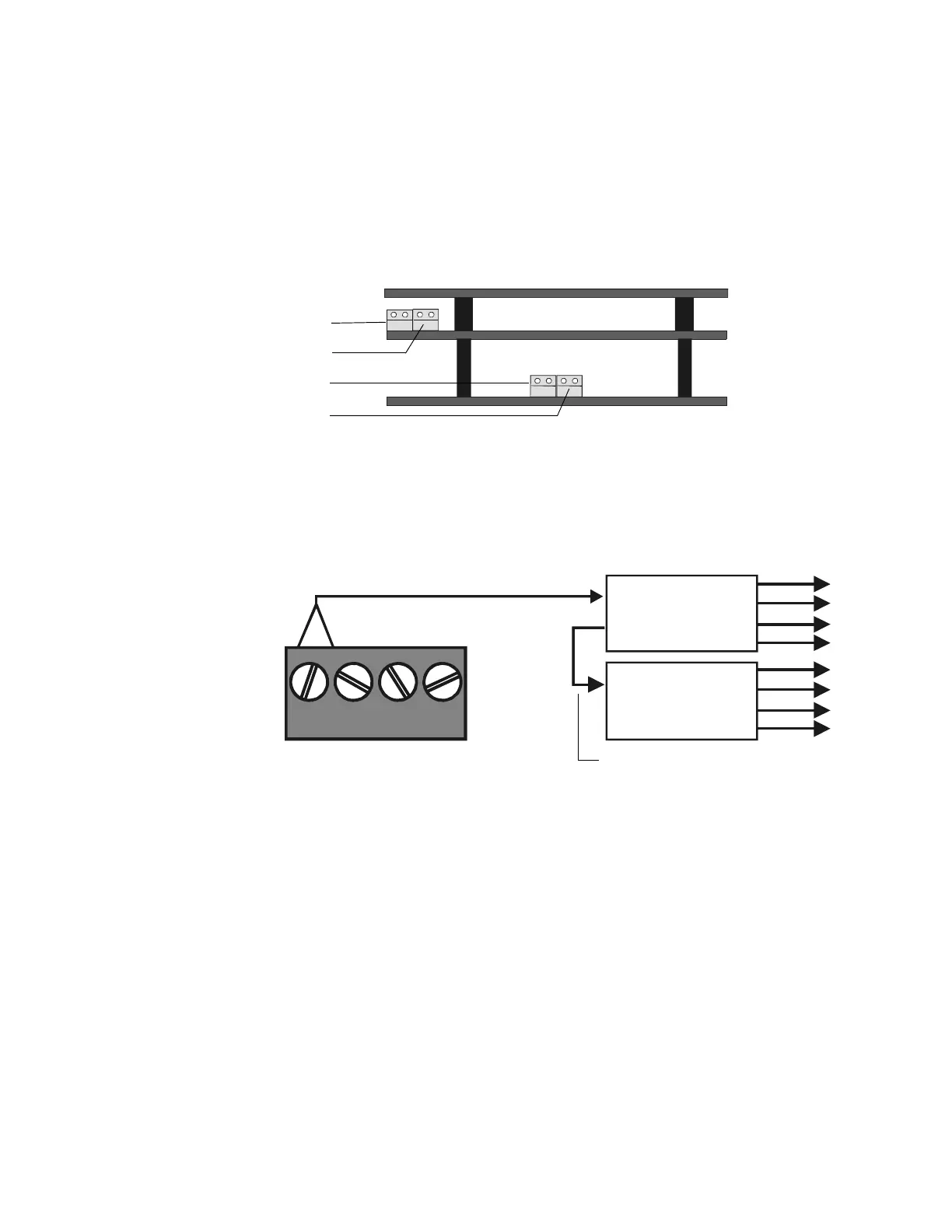
Shown below are the wire connectors on the bottom of the ICM-4RK and the ICE-4 modules.
Figure 23 ICM-4RK/ICE-4 Connectors
Power Supply Connections
The figure below illustrates typical connections from main power supply.
Figure 24 Main Power Supply Connection
Multiple Power Supplies
Cut JP1 and JP2 on ICM-4RK when supplying 24V power from two separate sources to the
ICM-4RK. ICM-4RK circuits 1-2 will receive their power from J5; ICM-4RK circuits 3-4 will
receive their power from J6.
Cut JP1 and JP2 on ICE-4 when supplying power from separate sources to expander circuits 5-8.
ICM-4RK circuits 5-6 will receive power from J5 on the ICE-4 and ICM-4RK circuits 7-8 will
receive power from J6 on the ICE-4.
See Figure 25 for jumper locations.
nfs640-icmconn.cdr
ICM-4RK
ICE-4
J5
J6
J5
J6
J5
ICM-4
J6
ICE-4
J5
TB7
24V 24V RESETNONRST
+ – + –
Power Cable P/N 71091
nfs640-icmnac.cdr
Eight NACs that
share 1.25 A
TB7 on Control Panel
Bell power cable (P/N 75400) or
alternate Power Harness (P/N 71093, with
lugs removed and wires stripped)
Black wire (–), Blue wire (+)

 Loading...


