Auxiliary Relay Module (ARM-4): Product-Specific Details Installation
NFS-640 Installation Manual P/N 51332:B1 12/01/2003 49
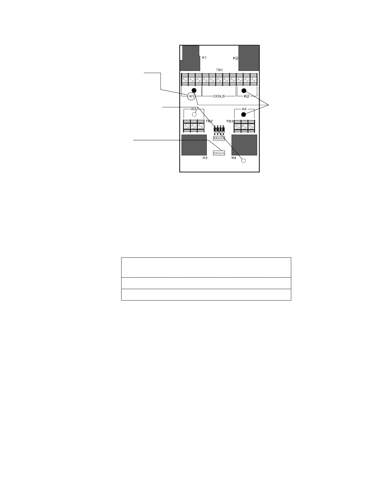
Figure 29 ARM-4 Stand-off & Terminal Locations
3.8.3 Field Wiring an Auxiliary Relay Module
The figure above shows terminal assignments for ARM-4 module control relays K1-K4, which
control nonpower-limited circuits. Power-limited and nonpower-limited circuit wiring must remain
separated by at least 0.25 inch (6.35 mm) within the cabinet and exit the cabinet though different
knockouts, conduits, or both.
Note: For more information, refer to Section 3.6 “UL Power-limited Wiring Requirements”.
The table contains contact ratings for relays K1-K4 on the ARM-4 module:
P2
P1
NC NO C
NC NO C
NC NO C
NC NO C
Com K1 K2 K3 K4
– + + + +
ARM-4.cdr
P-1
Connection for
Cable P/N 71092
These 3 holes for
support stand-offs.
These 2 holes for
mounting stand-offs.
Terminal
Assignments
(typ. 4 places)
Table 5 Contact Ratings for K1-K4 on the ARM-4 Module
Resistive Load
Contacts
Normally Open (N.O.) Normally Closed (N.C.)
125 VAC 20 A 10 A
30 VDC 20 A 10 A

 Loading...


