System Overview System Components
14 NFS-640 Installation Manual P/N 51332:B1 12/01/2003
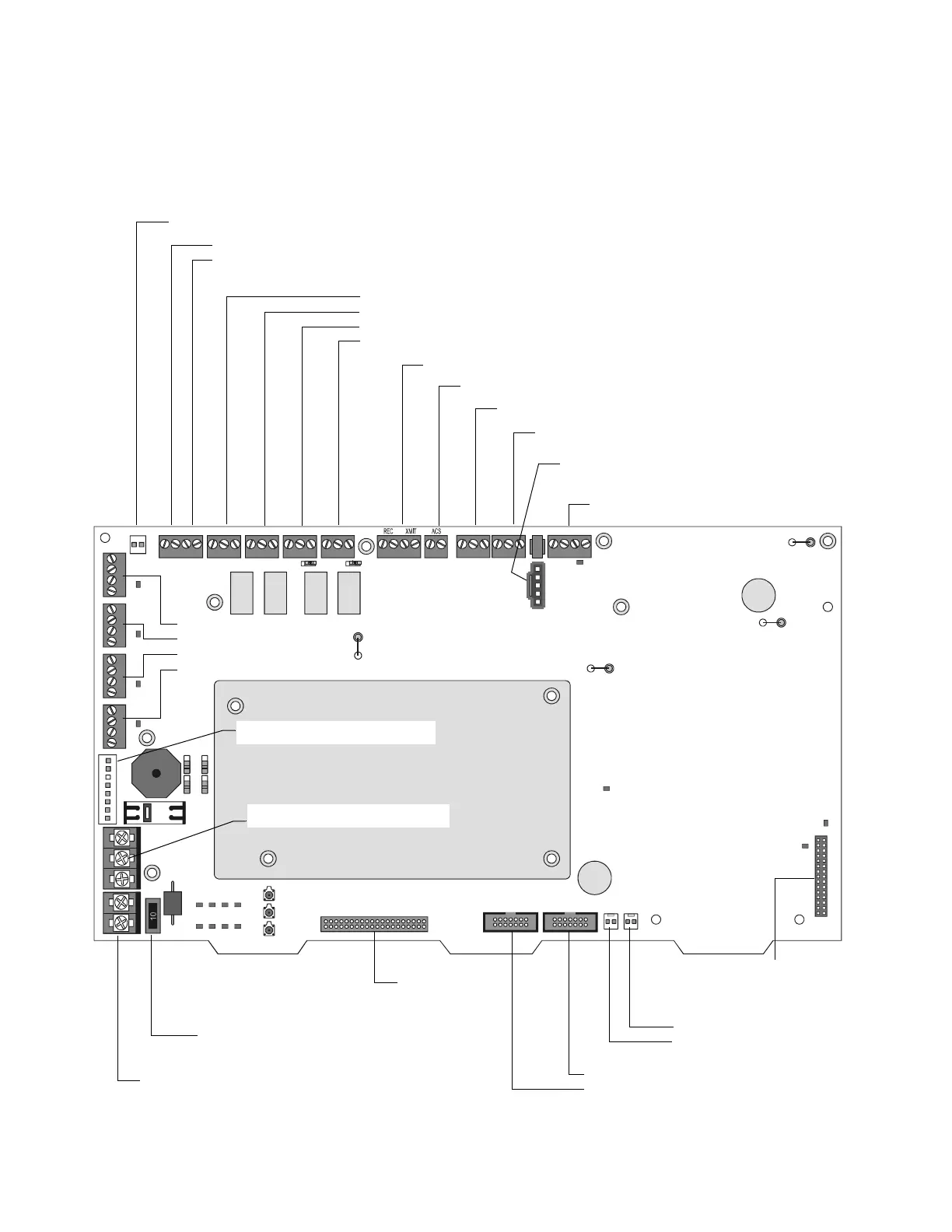
2.2.4 Circuit Board Components
The following two figures illustrate the location of the various connections, switches, jumpers and
LEDs on the circuit board. Figure 3 shows wiring connections. Figure 4 shows jumpers, LEDs and
switches. See Section 3 “Installation” for more details.
Figure 3 Circuit Board Components: Wiring Connections
NO NO NO NONC NC NC NCCCCC
+- +- + -+ -+ -
TX RX REF TX RX REF B+ A+ B- A-
EARTH NTRL HOTBATT+BATT- B+B- A+A- B+B- A+A- B+B-A+A- B+B- A+A-
J3 - LEM-320
Connector
(SLC Loop #2)
J5 - Panel Circuits (supervised)
J6 - Panel Circuits (supervised)
J10 - Security Tamper Switch
J11 - Auxiliary Trouble Input
J4 - KDM-2
Connection
TB1 - Battery Connection
(over-current protected)
TB6 - NAC#1
TB5 - NAC#2
TB4 - NAC#3
TB3 - NAC#4
10 Amp Slo-Blow Fuse
P/N 12067
J7 - Accessory Power Connection
TB2 - AC Power Connection
nfs640-board2.cdr
All NAC Circuits: power-limited, supervised
TB16 - SLC #1 Connections (Detectors,
Modules) (supervised)
TB15 - EIA-232 PC Terminal Connection
J1 - Network/Service Connection (NUP)
(power-limited, supervised)
TB14 - EIA-232 Printer Connection
TB12 - EIA-485 Terminal Mode Connection (supervised)
TB13 - EIA-485 ACS Mode Connection (supervised)
TB7 - DC Power (24 VDC power-limited, non-resettable)
TB7 - DC Power (24 VDC power-limited, resettable)
J8 - Zone Code Input
TB8 - Alarm Relay
TB9 - Trouble Relay
TB10 - Supervisory Relay
TB11 - Security Relay
See Section 3.5.13 “Output Relay
Connections” for details.

 Loading...


