Installing the Control Panel Installation
NFS-640 Installation Manual P/N 51332:B1 12/01/2003 33
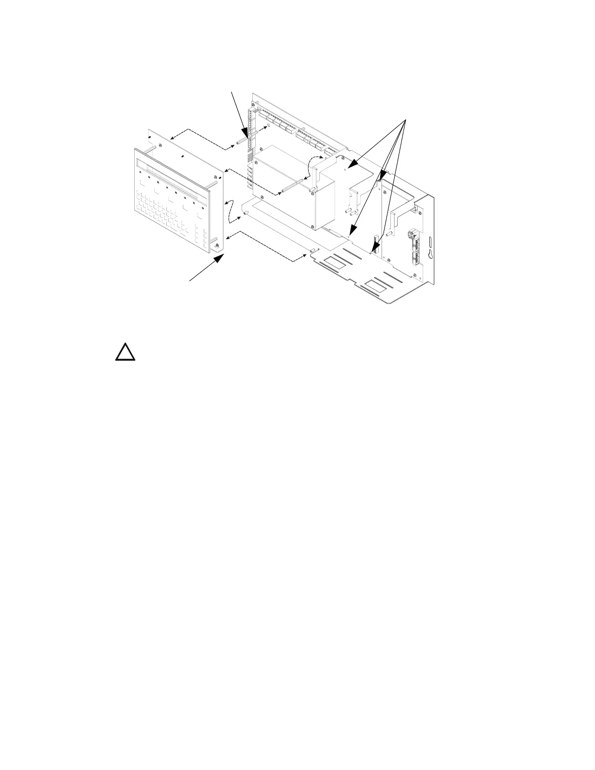
Figure 8 Locating and Aligning Stand-offs for Keypad/Display and Panel Circuits
(Chassis CHS-M2 shown)
3.5.2 Using NCA as Primary Display
The NFS-640 can be set up to use an NCA instead of a KDM-2. In this system design, connect the
network port on the NFS-640 (J1) directly to the network port on the NCA (J3); see the NCA
Manual for specific instructions.
Note: This system design is required in Canadian stand-alone applications.
If the NFS-640 and NCAare being used as a stand-alone pair, each device must be programmed
separately using VeriFire Tools in its off-line programming mode. Because the VeriFire Tools com-
puter also uses the network port, NFS-640 and NCA must be temporarily disconnected for pro-
gramming. If the NFS-640 with NCA is connected to a network, there are two additional options
for programming: either connect the VeriFire Tools programming PC to the network port on the
NCM board, or program the NFS-640 through another network node. (See VeriFire Tools on-line
help for details.)
!
CAUTION: It is critical that all mounting holes of the NFS-640 are secured with a screw or
standoff to insure continuity of Earth Ground.
Stack of two male-female stand-offs:
connect P/N 42185 (2.0 inch, 50.8 mm)
to P/N 42186 (1.312 inch, 33.33 mm).
Note: If not using this location,
secure these mounting holes
with screws.
Screw keypad mounting plate
to stand-offs on lip of chassis.
Lower edge of panel circuit modules slide
into chassis slots, and upper edge mounts
onto PEM studs on the chassis flange.
CHS-M2-11-03-assy.wmf

 Loading...


