Installation Auxiliary Relay Module (ARM-4): Product-Specific Details
48 NFS-640 Installation Manual P/N 51332:B1 12/01/2003
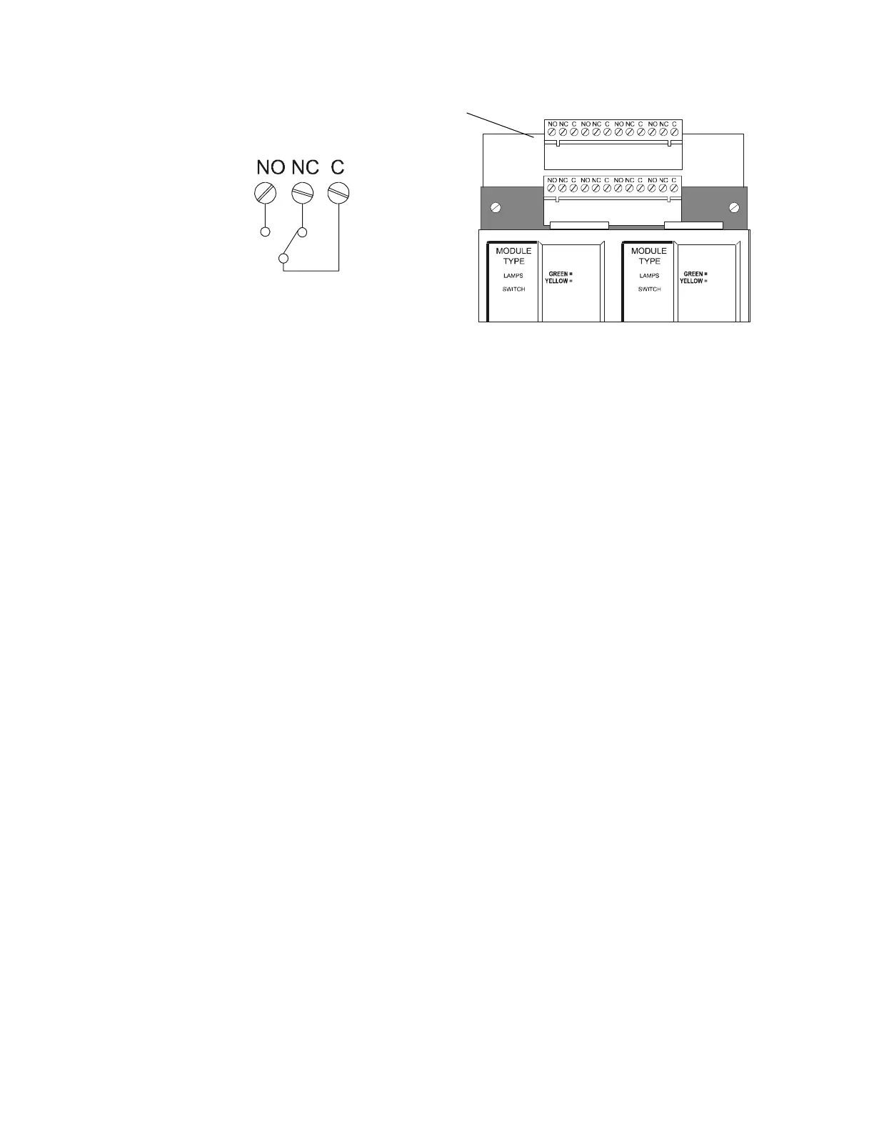
Figure 28 Field-Wiring a CRM-4RK or CRE-4 Module
3.8 Auxiliary Relay Module (ARM-4): Product-Specific Details
3.8.1 Overview
If a CRM-4RK/CRE-4 is to be incorporated into the control panel and an ARM-4 is being driven by
it, note the following:
• Each ARM-4 must be supported by one CRM-4RK or one CRE-4.
• If using ARM-4’s for both modules, mount two ARM-4’s in separate positions.
• If mounted in FACP enclosure keep all non-power limited wiring separate from power
limited wiring.
For ease of installation, service, and wiring mount the ARM-4 module in a position on the chassis
that will not have any other module or expander board in front of it. However, you can install the
ARM-4 directly behind the CRM-4RK or CRE-4.
ARM-4 mounts in the second, third or fourth row of a CAB-4 series backbox, against the back of a
chassis CHS-4 or CHS-4L. The ARM-4 may be mounted in any of the 8 adjacent backbox
positions the cable can reach.
3.8.2 Installation
To install the Auxiliary Relay Module in the chassis:
1. Select a mounting position for the module on the chassis.
2. Install two (2) mounting stand-offs onto the studs of the chassis, at the selected location, as
shown in Figure 12. Tighten securely.
3. Install three (3) support stand-offs, with screws, onto the PC board in the locations shown in
Figure 12 or in the two right-hand positions on the first row. Tighten securely.
4. Position module over the stand-offs on the chassis; fasten the module to the chassis with the
two (2) retaining screws. Tighten securely.
5. Connect one end of the Cable (P/N 71092) to plug P1 on the ARM-4.
Note: The other end of the cable is connected to jumper JP5 on the CRM-4RK or CRE-4.
6. Connect all available external wiring at this time. Refer to Section 3.8.3 “Field Wiring an
Auxiliary Relay Module”.
CONTROL
RELAY
CONTROL
RELAY
Optional CRE-4 Control
Relay Expander
CREEXPCO-RK.cdr
CRM-4RK
Typical connections for a
Form-C control relay in
normal position.

 Loading...


