EasyManua.ls Logo

NTI ENVIROMUX-5D - User Manual

Default Icon
135 pages
Print Icon
To Next Page IconTo Next Page
Loading...
MAN154 Rev Date 1/30/2014
ENVIROMUX-16D/-5D/-2D
Enterprise Environment Monitoring System
Installation and Operation Manual
ENVIROMUX
®
Series
Front View of ENVIROMUX-5D
Front View of ENVIROMUX-2D
Front and Rear View of ENVIROMUX-16D

Table of Contents

Questions and Answers

  • C
    Christopher TorresAug 17, 2025
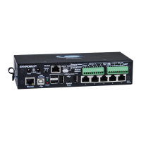
    Why am I not receiving email alert messages from my NTI Measuring Instruments?
    • O
      odanielsAug 17, 2025
      There might be several reasons why you are not receiving email alerts from your NTI Measuring Instruments ENVIROMUX. It could be due to a disconnected Ethernet cable, so check your Ethernet cable connections. Ensure that the IP address provided for the SMTP server is correct. Verify that your user profile is correctly configured, including group selections and contact settings. Also, the email address might not be accepted by the SMTP server due to server restrictions; check the SMTP server's policies.
  • E
    Edward SmithAug 19, 2025
    Why can't I access ENVIROMUX NTI Measuring Instruments through my browser?
    • C
      Cody MartinezAug 19, 2025
      If you cannot access the NTI Measuring Instruments ENVIROMUX through your browser, there are a few potential causes. First, the browser you are using might not be supported. Also, you might be trying to connect to the wrong IP address; ensure you're typing the correct IP address into your browser's URL field. Lastly, it's possible that your user account is not authorized; contact your administrator for the correct username and password.
  • W
    wsmithAug 22, 2025
    Why is the Device Discovery tool not working for my NTI Measuring Instruments?
    • A
      April GreeneAug 22, 2025
      If the Device Discovery tool isn't working for your NTI Measuring Instruments ENVIROMUX, it could be due to a couple of reasons. First, Java might not be installed on your system. Make sure you download and install Java. Another reason could be that your PC and the ENVIROMUX are on different physical networks; ensure they are both on the same physical network.
  • S
    Sarah LongAug 25, 2025
    What to do if I cannot access ENVIROMUX user interface with direct Ethernet connection on NTI Measuring Instruments?
    • P
      patriciacostaAug 26, 2025
      If you're unable to access the ENVIROMUX user interface with a direct Ethernet connection for your NTI Measuring Instruments, it could be because Telnet is not enabled. You must enable Telnet through the web interface. Another possible cause is that the cable is not wired correctly; ensure the cable is wired pin-to-pin (1 to 1, 2 to 2, etc.).
  • C
    Colin JohnsonAug 27, 2025
    What to do if ENVIROMUX NTI Measuring Instruments will not recognize sensor?
    • W
      williamsmatthewAug 28, 2025
      If your NTI Measuring Instruments ENVIROMUX is not recognizing a sensor, it could be that the previously used sensor port was never cleared from memory upon removal. To resolve this, click on “???” in the summary page, then click on “Configure“ button, and then click on “Remove” at the bottom of the Configure page to remove the sensor and clear the port.
  • R
    Ryan StanleyAug 30, 2025
    What does it mean if the “Pwr” LED is blinking on my ENVIROMUX-16D NTI Measuring Instruments?
    • A
      Amanda OwensAug 31, 2025
      If the “Pwr” LED is blinking on your ENVIROMUX-16D NTI Measuring Instruments, it indicates a specific condition. A blink rate of 1/sec means the power is off, and the battery backup is powering the ENVIROMUX; restore AC power to resolve this. Rapid blinking indicates the discovery tool is in use; there is nothing wrong, simply close the Discovery Tool to stop the blinking.
  • M
    Mary AlexanderSep 2, 2025
    Why do sensors connected to RJ45 Sensor ports stop working on my NTI Measuring Instruments?
    • L
      luis92Sep 2, 2025
      If sensors connected to the RJ45 Sensor ports stop working on your NTI Measuring Instruments ENVIROMUX, it may be because the sensors applied collectively exceed the current rating. Disconnect the sensors and wait approximately 10 minutes for the fuse inside the ENVIROMUX to reset. For ENVIROMUX-16D, ensure the load of all 8 sensors per row does not exceed 500 mA.
  • M
    Michelle YoungSep 5, 2025
    How to troubleshoot not receiving e-mail alert messages on NTI Measuring Instruments?
    • M
      Michael BensonSep 5, 2025
      There might be several reasons why you are not receiving email alerts from your NTI Measuring Instruments ENVIROMUX. It could be due to a disconnected Ethernet cable, so check your Ethernet cable connections. Ensure that the IP address provided for the SMTP server is correct. Verify that your user profile is correctly configured, including group selections and contact settings. Also, the email address might not be accepted by the SMTP server due to server restrictions; check the SMTP server's policies.
  • K
    Katherine CochranSep 7, 2025
    What to do if the beacon is not illuminating on NTI Measuring Instruments?
    • D
      darlene56Sep 8, 2025
      If the beacon is not illuminating on your NTI Measuring Instruments, check the wire connections to ensure they are properly connected. Make sure the beacon is rated at 12VDC, 180mA or less. Also, verify the sensor configuration to ensure the beacon is selected under “Alert Notifications” (-16D).
  • J
    Jennifer LeeSep 12, 2025
    What to do if the siren is not making noise on NTI Measuring Instruments?
    • D
      Denise JohnsonSep 12, 2025
      If the siren is not making noise on your NTI Measuring Instruments, check the wire connections to ensure they are properly connected. Ensure the siren in use is rated at 12VDC, 180mA or less. Also, check the sensor configuration to ensure the siren is selected under “Alert Notifications” (-16D).

Summary

Introduction

Features

Lists key capabilities of the ENVIROMUX system, including monitoring, alerts, user management, and connectivity.

Materials

Materials Included with ENVIROMUX-16 D Kit

Lists the components included in the ENVIROMUX-16D kit, such as the system, power cord, cables, and CD.

Materials Included with ENVIROMUX-5 D Kit

Lists the components included in the ENVIROMUX-5D kit, including AC adapter and cables.

Materials Included with ENVIROMUX-2 D Kit

Lists the components included in the ENVIROMUX-2D kit, such as AC adapter and cables.

Materials Required for Connection

Lists cables and connectors that are not supplied with the unit but are needed for setup.

Supported Web Browsers

Installation

Mounting Instructions-16 D

Details on how to mount the ENVIROMUX-16D unit in a rack or on a shelf using provided hardware.

Mounting Instructions-5 D; -2 D

Instructions for mounting the ENVIROMUX-5D and -2D units, including wall or Zero-RU rack mounting.

Sensor Attachment

RJ45 Sensor Ports

Connects external sensors with RJ45 connectors to the ENVIROMUX unit. Details power limits.

Digital In Terminals

Liquid Detection Sensors

Alarm(Beacon;Siren) Connections

Connect Output Devices

Terminal Connection for RS232

Connect a terminal for direct RS232 serial communication

Connects a PC to the ENVIROMUX via RS232 port using a CAT5 cable and adapter.

Connect a terminal using USB Console port

Connects a PC to the ENVIROMUX via USB Console port using a USB cable.

Ethernet Connection for Remote User Control

Modem Connection

USB GSM Modem

Connects a USB GSM modem for SMS alerts and data transfer. Lists compatible modems.

3 G Data Transfer And SMS Messaging

Configures the modem for 3G data and SMS messaging for alerts.

3 G Data Transfer, SMS Messaging, and Web Interface

Uses modem for data, SMS, and web interface access.

Serial GSM Modem

Power Connection-ENVIROMUX-16 D

Dual Power Option

Connects ENVIROMUX-16D to two separate power sources for redundancy.

DC Power Option

Power Connection- ENVIROMUX-5 D;-2 D

ENVIROMUX-5 D-48 VDP Specifications

Power connections on ENVIROMUX-5 D-48 VDP

Details DC power options for ENVIROMUX-5D-48VDP, including dual power.

Power Supply sensors-Summary Page

Displays power supply status, including DC connections.

Remote RS232 Device Control

Connect serially controlled device

Connects a remote serial device to the ENVIROMUX's RS232 AUX port.

Create user rs232

Sets up a user account named "rs232" for remote serial control.

Overview - Use and Operation

Sensors

Describes sensor types, connection methods (RJ45, terminal blocks), and their configuration.

IP Assignment

How to assign an IP address to the ENVIROMUX via Discovery Tool, web interface, or RS232.

User Management

Manages user accounts, privileges, and access levels for the ENVIROMUX.

Alerts

Configures notification methods, thresholds, and alert delays for sensors.

Overview - Use and Operation

Data and Event Logging

Logs sensor readings, alerts, user logins, and other system events. Supports email/SNMP alerts.

Email

Configures ENVIROMUX to send email alerts via SMTP server.

Syslog

Configures ENVIROMUX to send alerts as Syslog messages.

SNMP

Configures ENVIROMUX to send alerts as SNMP traps.

Modbus TCP;IP Support

Enables PLC control using Modbus TCP/IP for sensors and relays.

External Modem

Connects an external GSM modem for SMS alert notifications.

Power-on;Reset Operation

Describes system startup, monitoring application launch, and alert reporting.

Out-of-Box Operation

Initial setup and configuration before network settings are assigned.

Device Discovery Tool

Use and Operation via Web Interface

Log In and Enter Password

Accessing the ENVIROMUX web interface by logging in with username and password.

Summary page

The initial page displaying an overview of monitored items and system status.

Monitoring

Summary Page

Power Supplies

Power Supply Status- Dual Power model

Shows the status of power supplies, including alerts and recent alert times.

Power Supply Alert Configuration-part 1

Configures alert settings for power supplies, including groups and notification methods.

Internal Sensors

External Sensors

RS485 Sensors

Lists supported RS485 sensor types (Temperature, Humidity, Current, etc.).

RS485 Sensor Management

How RS485 sensors are detected, identified, and displayed in the web interface.

External Sensor Reading

Sensor Configuration Page (1)

Sensor Configuration Page (2)

Sensor Configuration Page (3)

Sensor Configuration Page (4)

External Sensor Configuration

Configures external sensor settings such as description, units, levels, thresholds, and refresh rate.

Sensor Configuration

Schedule Settings

Configures the schedule type, start/end days, and hours for sensor alerts.

Alert Settings (Applies to Critical and Non-Critical Alerts except where noted)

Detailed alert settings including disabling alerts, delay, notifications, and IP camera captures.

Alert Settings (Applies to Critical and Non-Critical Alerts except where noted) (Cont’d)

Test Alerts

How to test configured alert notifications using the "Simulate Alert" button.

Alert Settings

Specialized Sensors (for S420 MA-24 V Current Sensor Configuration only)

RTD Sensor Configuration (Type: Temperature)

Configures an RTD temperature sensor connected via a current sensor input.

Contact Sensors

Add a Contact Sensor to RJ45 Sensor port

Manually add contact sensors to RJ45 ports and configure their properties.

Contact Sensor configuration page

Digital Inputs

Digital Input Sensors

Lists digital input sensors and provides links to add new ones or configure existing ones.

Add New Digital Input

Adds a new digital input sensor by selecting a connector and assigning properties.

Status of Digital Input #2

Open configuration from Digital Input page

Cycle Sensor Power

Add Tach Sensor

Monitor Output Relay

Output Relays

Lists output relays and their status (active/inactive), with options to view or edit.

Output Relay Status

Manually set the state of an output relay (activate/deactivate).

Configure Output Relay

IP Devices

IP Devices monitored

Lists monitored IP devices, their status, and actions like view or edit.

Add new IP Device

Adds a new IP device to be monitored by the ENVIROMUX.

IP Device Configuration

IP Device Configuration-more

Network Setup

Group Settings

Assigns IP devices to groups for alert message delivery.

Schedule Settings

Configures schedule types, start/end days, and hours for IP device alerts.

Alert Settings

Configures alert notifications for IP devices, including disabling alerts and notification methods.

IP Cameras

Monitoring IP Cameras

Displays video snapshots from up to 8 monitored IP cameras.

IP Camera Configuration

Configures IP camera settings like name, URL, IP address, and refresh rate.

Administration

System Configuration

Configures system settings like time zone, date, time, NTP server, and backup/restore.

System Configuration

Time Settings

Configures time zone, daylight saving, date, time, NTP sync, and email/SMS time stamps.

Configuration Backup & Restore

Saves and restores ENVIROMUX configuration settings.

USB LCD Display

Auxiliary Serial Port Configuration (“RS232 AUX”)

System Configuration-continued

RSA Public Key

Saves an authentication key for remote SSH commands from Linux/Unix machines.

Alert E-mail Format

Customizes the content of alert emails by omitting certain information.

Administration-Enterprise Setup

GSM Modem Status

Enable SMS Relay

Administration- Network Setup

Network Setup

Configure SMTP, SNMP, and security settings

Configures SMTP server for emails, SNMP agent, and server security settings.

Configure 3 G Data Connection

X509 Certificate

X509 Client Authentication

Enables X509 client certificate authentication for secure web access.

IP Filtering

System Information

Administration- Firmware

Update Firmware

Uploads new firmware to the ENVIROMUX to update features or fix issues.

Advanced-Cascade Configuration

Cascade Configuration

Configure which Slaves will be connected to the Master

Selects and configures slaves (Ethernet or RS485) that will be connected to the master unit.

Apply alert settings to alert for Slave connection loss

Configures alerts on the master unit for slave unit communication loss.

Portion of Summary Page from a Master with a Slave

Reboot the System

Smart Alerts

Events used for Smart Alerts

Introduces the concept of events as sensor conditions for Smart Alerts.

Sensor to be used for a predefined event

Selects a sensor to associate with a predefined event for triggering alerts.

Configuration options for new event

Event Configuration options continued

Smart Alert summary page

Smart Alert configuration

Event Logical Function Diagram

LOG

View Event Log

Views a log of system events like startups, shutdowns, logins, and alerts.

View Data Log

Views data readings from sensors and IP devices.

Log Settings

Configures how logs are sent, their capacity handling, and user notifications.

Event Log page

Data Log page

Log Settings

Log to USB Flash Settings

Support

Logout

FRONT PANEL CONTROLS AND LED INDICATORS

Front Panel LED Status Chart

Explains the meaning of each LED indicator on the ENVIROMUX front panel.

System Reset Button

Describes the function and usage of the system reset button for rebooting the unit.

Alarm Test;Silence Button

Restore Defaults Button

BATTERY BACKUP

ENVIROMUX-16 D

Details the sealed lead-acid battery backup for the ENVIROMUX-16D.

ENVIROMUX-5 DB; -2 DB

Details the sealed lead-acid battery backup for the ENVIROMUX-5DB/-2DB.

USB PORT

SERIAL CONTROL

MODBUS TCP;IP SUPPORT

Modbus TCP Function Codes Definition

Defines Modbus TCP function codes for reading/writing data and relay states.

Function Code 01 - Read the state of Output Relays

Explains how to read the status of output relays using Modbus Function Code 01.

Function Code 02 - Read the state of Digital Inputs

Function Code 04 - Read Internal;External Sensors floating point values

Write data to force multiple Output Relays Active;Inactive

HOW TO SETUP EMAIL

Configure user to receive alerts via email

HOW TO SETUP SNMP

SNMP Settings under Network Settings

Enables SNMP agent and traps, and sets community names in network settings.

Enter at least one group number to sensor configuration

Assigns sensors to groups for receiving alert messages via SNMP.

Enable SNMP Traps for the sensor

User Settings required for SNMP Traps

Username must match SNMP configuration

Apply applicable authentication settings

HOW TO SETUP SYSLOG

Configure which group(s) a sensor will belong to

Assigns sensors to groups for sending Syslog messages.

Enable Syslog alerts for the sensor

Enables Syslog alerts for sensors on their configuration pages.

Configure user to receive alerts via Syslog

Configure sensor readings to be added to data log

Configure data logs to send Syslog messages

LOCATING OIDS

ENVIROMUX-16 D SPECIFICATIONS

Front Panel Interface

Details the LEDs, USB ports, and buttons on the ENVIROMUX-16D front panel.

RJ45 Sensor Inputs

Specifies connector type, voltage, current, signal type, cable length, and protection for RJ45 sensor inputs.

Digital Inputs

Details connector, wire range, voltage, resistance, and protection for digital inputs.

Output Relays

Specifies connector, wire range, output type, rating, resistance, and protection for output relays.

Beacon Port & Siren Port

Details connector, wire range, voltage, current, protection for beacon and siren ports.

USB Device Ports

Specifies connector type and version for USB device ports.

USB-Serial Port “Console”

Details console port specifications for ENVIROMUX-16D.

Auxiliary Power Port

Specifies connector, wire range, voltage, current, and protection for auxiliary power ports.

Ethernet Port

Details connector, speed, security, and supported protocols for the Ethernet port.

General Specifications

Lists power input, operating temperature, humidity, MTBF, and enclosure size.

TCP;IP

Lists supported browsers, network configuration options, and max email addresses.

ENVIROMUX-5 D SPECIFICATIONS

User Interface

Describes the LEDs on the ENVIROMUX-5D front panel for power and fault status.

RJ45 Sensor Inputs

Specifies RJ45 sensor input details for ENVIROMUX-5D.

Digital Inputs

Details digital input specifications for ENVIROMUX-5D.

Output Relays

Specifies output relay details for ENVIROMUX-5D.

Alarm Port

Details the alarm port specifications for ENVIROMUX-5D.

USB Device Ports

Specifies USB device port details for ENVIROMUX-5D.

USB-Serial Port “Console”

Details console port specifications for ENVIROMUX-5D.

ENVIROMUX-5 D SPECIFICATIONS

Auxiliary Power Port

Specifies auxiliary power port details for ENVIROMUX-5D.

Ethernet Port

Details Ethernet port specifications for ENVIROMUX-5D.

General Specifications

Lists general specs for ENVIROMUX-5D.

TCP;IP

Lists TCP/IP specs for ENVIROMUX-5D.

Optional Battery

Details the optional battery specifications for ENVIROMUX-5D.

ENVIROMUX-2 D SPECIFICATIONS

User Interface

Describes the LEDs on the ENVIROMUX-2D front panel for power and fault status.

RJ45 Sensor Inputs

Specifies RJ45 sensor input details for ENVIROMUX-2D.

Digital Inputs

Details digital input specifications for ENVIROMUX-2D.

Output Relays

Specifies output relay details for ENVIROMUX-2D.

USB Device Ports

Specifies USB device port details for ENVIROMUX-2D.

USB-Serial Port “Console”

Details console port specifications for ENVIROMUX-2D.

Auxiliary Power Port

Specifies auxiliary power port details for ENVIROMUX-2D.

ENVIROMUX-2 D SPECIFICATIONS

Ethernet Port

Details Ethernet port specifications for ENVIROMUX-2D.

General Specifications

Lists general specs for ENVIROMUX-2D.

TCP;IP

Lists TCP/IP specs for ENVIROMUX-2D.

Optional Battery

Details the optional battery specifications for ENVIROMUX-2D.

WIRING METHODS

RS485 Sensor Cable

Wiring standards (EIA/TIA 568 B) for CAT5 cables connecting ENVIROMUX and RS485 sensors.

Contact Sensor Wiring

Socket-to-sensor wiring for contact sensors plugged into RJ45 sensor sockets.

TROUBLESHOOTING

RECYCLING INFORMATION

INDEX

WARRANTY INFORMATION

NTI ENVIROMUX-5D Specifications

General IconGeneral
ModelENVIROMUX-5D
Product TypeEnvironmental Monitoring System
Number of Inputs/Sensor Ports5
Number of Sensors Supported5
Humidity Range0% to 100% RH
Communication InterfaceEthernet
Operating Temperature0°C to 50°C
Sensor Types SupportedTemperature, Humidity, Water, Smoke
ProtocolsHTTP, HTTPS, SNMP, SMTP
Alert TypesEmail, SMS, SNMP traps
Power Supply/Source12V DC

Related product manuals