UG8000-00 November 2002
Page 1-12
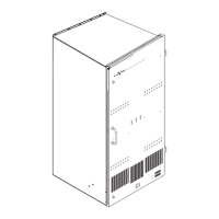
NV6128 Rear Panel
Figure 1-5 illustrates the NV6128 rear panel. The rear panel contains the following
connectors:
X
128 Dual Output (A - non-inverted, and B - inverted) Matrix BNC
connectors (256 total).
Y
128 Input Matrix BNC connectors.
Z
IEC Standard AC power connectors for Main Power Supply 1 and 2 and
Redundant Power Supply 1 and 2.
[
Power Supply Alarm Connectors. For connection details, see the heading,
"Power Supply Alarms Connector (6064/6128)" on page 1-33.
\
System Alarms connector. For connection details, see the heading,
"Alarms Connector (all models)" on page 1-31.
]
Monitor outputs (optional). Outputs 1 and 2 are identical SWB signals.
Outputs 3 and 4 are identical SD signals.
^
Video Reference 1 and 2. Connect analog PAL or NTSC composite video.
_
Ethernet and SMS7000 GSC Node Bus control system connectors. Ethernet
connectors may be used for the NVISION NV9000 Series Control System
and the GSC connector may be used for the GVG SMS7000 Control System.
See the documentation for those systems for connection details.
`
Serial Control and Diagnostic connectors. Connect your main
control system to the Primary and Secondary CTRL 1 connectors.
This provides control connections to the primary and secondary
Controller modules. If you have a second alternate control system,
use the Primary and Secondary CTRL 2 connectors.
Use the DIAG connectors for connecting to a PC to run the supplied
UniConfig router configuration software.
See Figure 1-11 on page 1-29 for Control connector drawings and
pin-outs, which are the same for all four control connectors. See the
UniConfig manual for the diagnostic port pin outs.
Note: Connectors not described here are reserved for future use.
 Loading...