Board Interface Connector
MPC5777C EVB User Guide, Rev. 1
19 NXP Semiconductors
The connection of any power domain and interfaces to Power SBC has to be enabled by respective
jumper as described in Table 10.
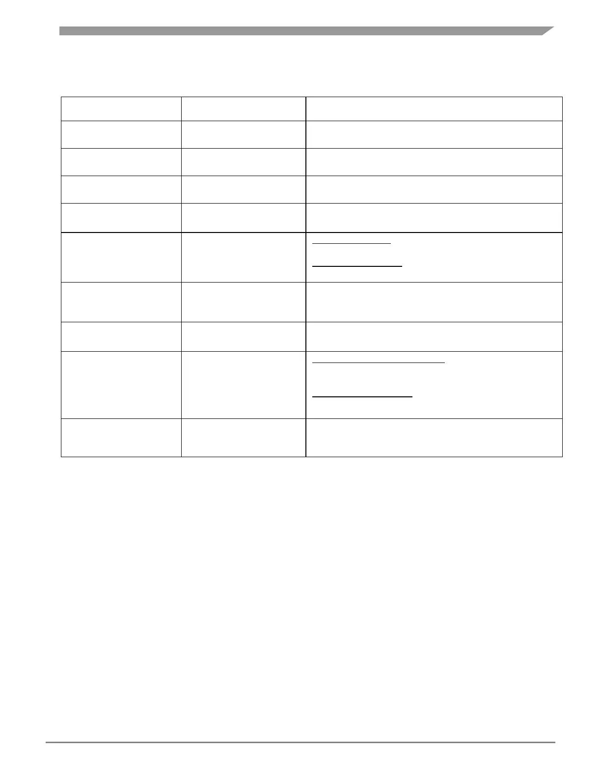
Table 10:
MCU power selection jumpers with PowerSBC
1-2: 3.3 V from onboard Power SBC to MCU
1-2: 5 V from onboard Power SBC to MCU
ADC Analog Supply
Selection
2-3: Select 5 V from Switching Regulator
VDD Core Supply
Selection
1-2: 1.25 V from onboard Power SBC to MCU
PowerSBC VCCA selection
& Current Driving Capability
J504: 2-3, J505:1-2:
SBC_3V3 with External PNP Transistor (upto 300mA)
J504: 1-2, J505: Open:
SBC_3V3 with internal MOSFET (up to 100mA)
MISO Buffer Supply
(SPI Bus level to connect
with MCU)
1-2: Select SBC 3.3 V
2-3: Select SBC 5 V*
Open: Normal Operation
Short: Enters into Debug Mode at Start-up
SPI Bus Selection from
SBC/ Mother Board
Connect Power SBC SPI to MCU:
1-2, 4-5, 7-8, 10-11, 13-14, 16-17
Connect MB SPI to MCU:
3-2, 6-5, 7-8, 12-11, 15-14
SBC RESET & Interrupt
Signals
1-2: Connect SBC Interrupt to MCU
3-4: Connect SBC RESET Output to MCU
NOTE
The PowerSBC does not connect to the 5.0V_LR power rail which is
powered by 5 V linear regulator when used with the motherboard. This
rail is powering the VDDA_SD & VDDA_EQ (ADC supply) and
VRH_SD, VRH_SEQ (ADC reference voltage). When using the
daughter card standalone (without the motherboard) it is required to
connect the 5.0V_LR and the 5.0V_SR rail as mentioned in Table 10 in
order for the microcontroller to come out of reset.
Power SBC has High Speed CAN Transceiver & LIN Transceiver. CAN bus from SBC is terminated
with DB9 connector (J508) and LIN is terminated with 4-pin Molex connector (J503) in the Daughter
Card.
The connections of the J508 (CAN) from PowerSBC are detailed in Figure 13.

 Loading...


