43856301TH Rev.3
15 /
Oki Data CONFIDENTIAL
1. Configuration
1.5.3 Specification of parallel interface
1.5.3.1 General of parallel interface
Spec.
IEEE1284-1994 conforming parallel interface
1.5.3.2 Connector and cable of parallel interface
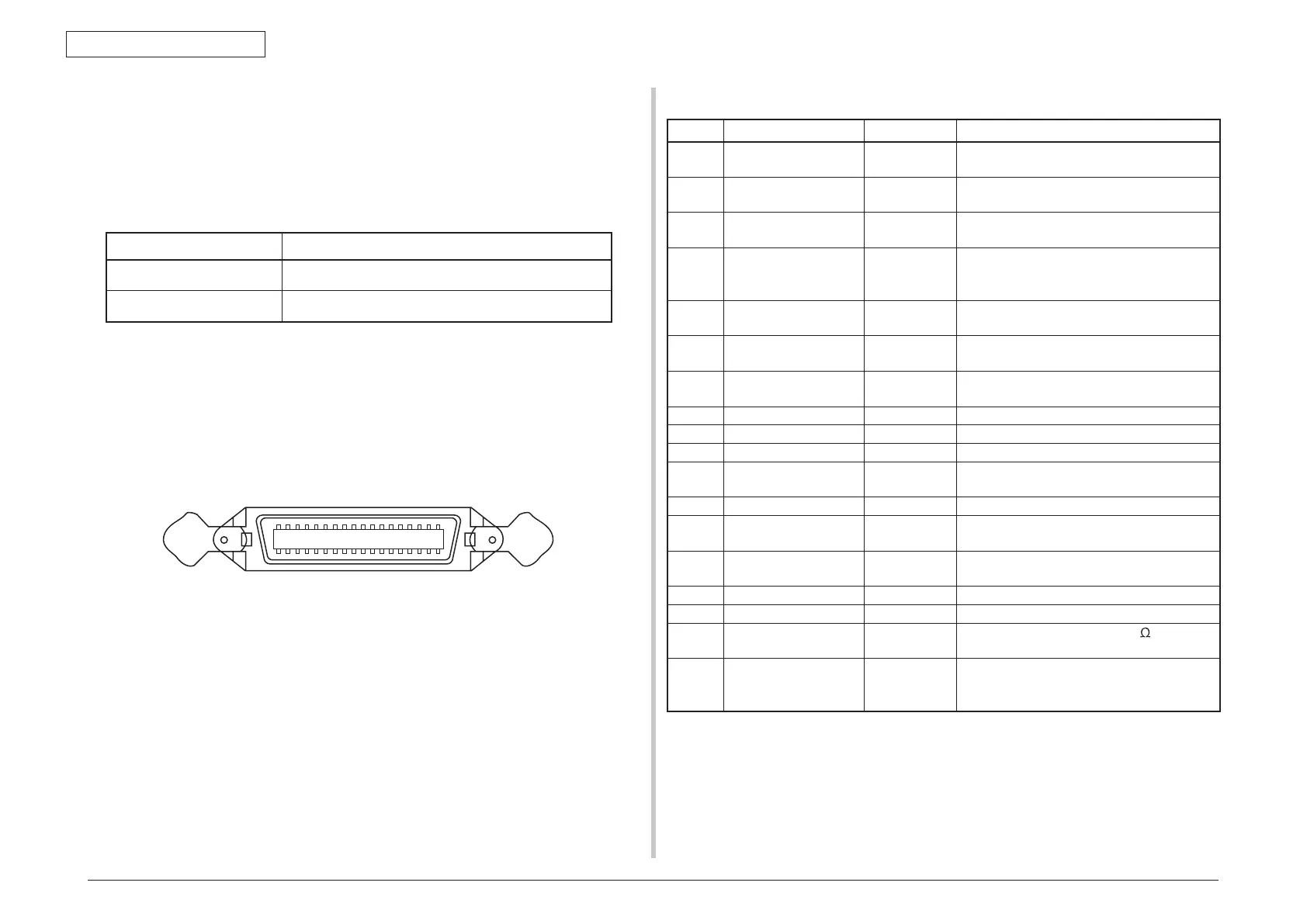
(1) Connector
Printer side : 36-Pole connector (Female)
57LE-40360-12(D56) (made by DDK) equivalent goods
Cable side : 36-Pole connector (male)
57FE-30360-20N(D8) (made by DDK) equivalent goods
Item Content
Related mode Compatible mode, nibble mode, and ECP mode
Data bit length Compatible: 8, nibble: 4, ECP: 9bit
Pin layout seen from interface cable side
(2) Cable
IEEE1284-1994 cab
le of less than 1.8m is used.
(For avoiding noise interference, please use shielded cable with the twisted-pair wire.)
1.5.3.3 Parallel interface level
Low level 0.0V~+0.8V
High level +2.4V~+5.0V
Pin NO. Name of signal Direction Function
1 nStrobe (HostClk) TO PRINTER It is a pulse to read data. Data is read by
posterior end.
2~9 DATA 1~DATA 8 Bi-direction It is parallel data of 8 bits. The high level
is “1", and the Low level is “0".
10 nAck(PtrClk) FROM
PRINTER
It is a signal that shows the data
reception completion.
11 Busy(PtrBusy) FROM
PRINTER
It is a signal that shows if the printer
is receiving the data. Data cannot be
received when it is at the high level.
12 PError(AckDataReq) FROM
PRINTER
The paper error is shown when it is at
the high level.
13 Select(Xflag) FROM
PRINTER
When parallel interface is effective, it is
always in high-level state.
14 nAutoFd(HostBusy) TO PRINTER It is used by the bidirectional
communication.
15 - - Not use
16 GND - Signal ground
17 FG - Chassis ground
18 +5V FROM
PRINTER
It cannot supply power outside.
19~30 GND - Signal ground
31 nInit(nInit) TO PRINTER The printer is initialized with the low
level.
32 nFault(nDataAvail) FROM
PRINTER
When the printer is in alarm state, it
becomes low level.
33 GND - Signal ground
34 - - Not use
35 HILEVEL FROM
PRINTER
It is pulled up to +5V at 3.3K
in the
printer.
36 nSelectIn
(IEEE1284 active)
TO PRINTER It is used by bidirectional communication.
It must be low level when it is in
compatible mode.
1.5.3.4 Signal of interface
Notes! • The signal name showed in the bracket is a signal name in nibble
mode.
• It only describes the function in compatible mode.
• The nibble mode of IEEEstd1284-1994 regulated by Institute
of Electrical and Electronics Engineers is supported. Using the
computer and the cable unsupported this standard may lead to
unexpected operation.