43856301TH Rev.3
67 /
Oki Data CONFIDENTIAL
4. Component replacement
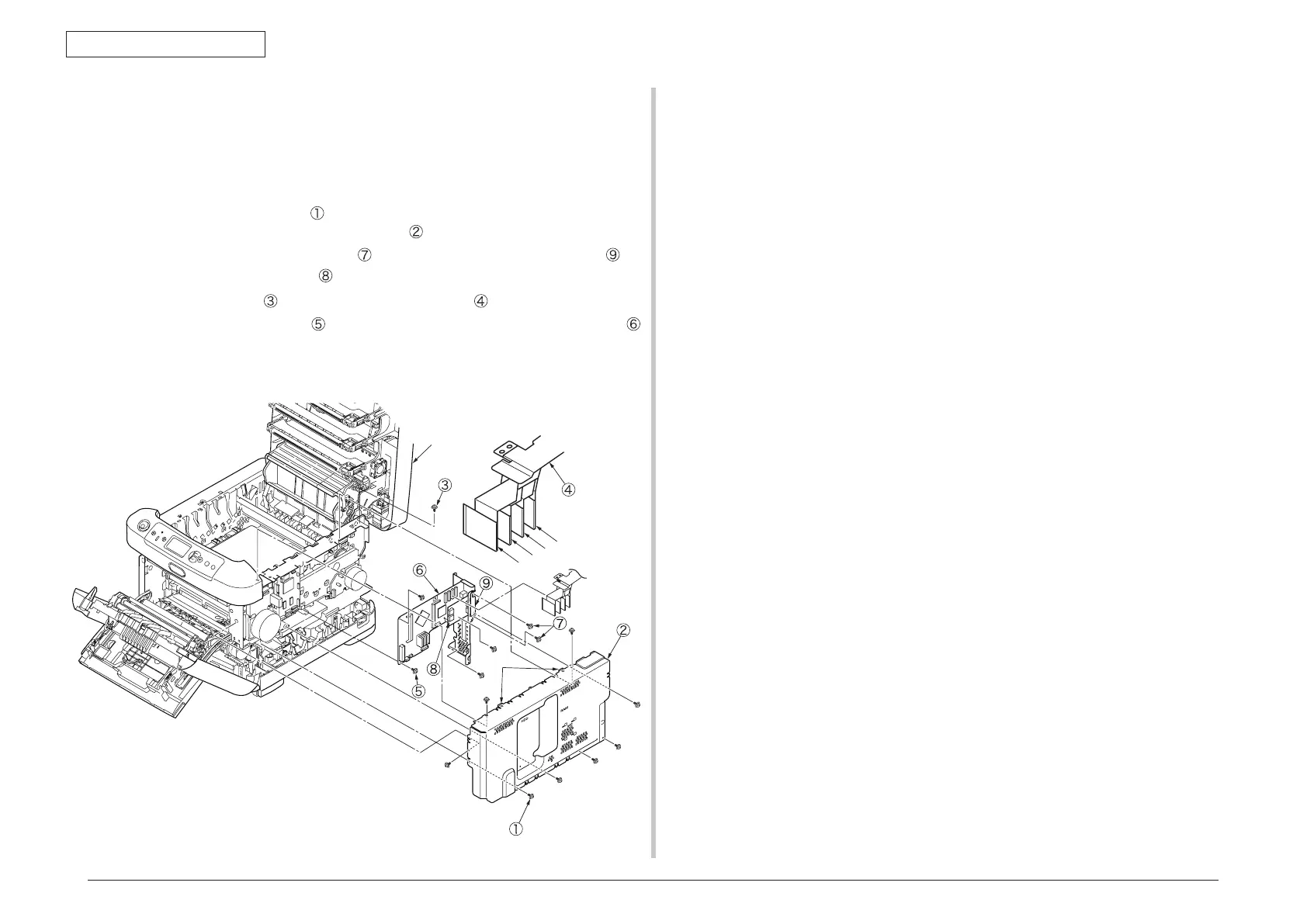
4.2.8 Control PCB
(1) Open the top cover.
(2) Remove the right side cover. (See section 4.2.4)
(3) Remove the Rear cover. (See section 4.2.6)
(4) Remove the eight screws
(silver), remove the connector and disengage the
claw A to take the plate-shield-Assy (PCL)
out.
(5) Remove the two screws (silver)
, and remove the HOST USB PCB by
holding the tip of nylon stud with a pair of pliers.
(6) Remove the screw
and disconnect the head cable .
(7) Remove the seven screws
(silver) and all cables, and take the control PCB
out.
Note! T
o attach the head cable, insert the end of the film-FG inside the plate-
side-R, preventing from touching the edge of the plate-side-R.
C
M
Y
K
×7
×8
Top cover
Claw A