43856301TH Rev.3
4 /
Oki Data CONFIDENTIAL
Index
1. Configuration ...........................................................................6
1.1 System configuration ............................................................................................7
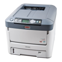
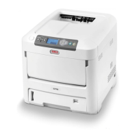
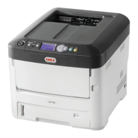
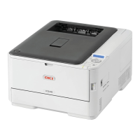
1.2 The Configuration of printer ..................................................................................8
1.3
Optional parts .......................................................................................................9
1.4
Specifications .....................................................................................................10
1.5
Specification of interface ....................................................................................13
1.5.1
Specification of USB interface ....................................................................13
1.5.1.1
General of USB interface .....................................................................13
1.5.1.2
Connector and cable of USB interface .................................................13
1.5.1.3
USB interface signal ............................................................................13
1.5.2
Specification of network interface ...............................................................14
1.5.2.1
General of network interface ................................................................14
1.5.2.2
Connector and cable of network interface ...........................................14
1.5.2.3
Signal of network interface ..................................................................14
1.5.3
Specification of parallel interface ................................................................15
1.5.3.1
General of parallel interface .................................................................15
1.5.3.2
Connector and cable of parallel interface ............................................15
1.5.3.3
Parallel interface level ..........................................................................15
1.5.3.4
Signal of interface ................................................................................15
2. Operating instructions ..........................................................16
2.1 Electrophotographic processing mechanism ......................................................17
2.2 Printing process ..................................................................................................21
3. Set up .....................................................................................32
3.1 Notes and precautions ........................................................................................33
3.2 Unpack method ..................................................................................................34
3.3
Setting method ...................................................................................................35
Set space ................................................................................................................35
3.4
List of equipments and accessories ...................................................................36
3.5
Assembling method ............................................................................................37
3.5.1
Assemble the main body of the printer .......................................................37
3.5.2
Cable connect .............................................................................................43
3.5.3
Optional part installation and confirmation ..................................................45
3.6
Setting content print (Configuration) ...................................................................56
3.7
Connecting method ............................................................................................57
3.8
User used Paper confirmation ............................................................................59
4. Component replacement ......................................................60
4.1 Precautions on component replacement ............................................................61
4.2 Method of component replacement ....................................................................63
4.2.1
Belt unit .......................................................................................................63
4.2.2
Fuser unit ....................................................................................................64
4.2.3
Left side cover .............................................................................................64
4.2.4
Right side cover ..........................................................................................65
4.2.5
Faceup tray ................................................................................................65
4.2.6
Rear cover...................................................................................................66
4.2.7
LED Assy/ LED Assy spring........................................................................66
4.2.8
Control PCB ................................................................................................67
4.2.9
Print engine controller PCB.........................................................................68
4.2.10 Top cover Assy ............................................................................................69
4.2.11 Top cover ....................................................................................................70
4.2.12 Control panel Assy .....................................................................................70
4.2.13 Board PRG/ LCD ........................................................................................71
4.2.14 Frame panel Assy .......................................................................................72
4.2.15 Low voltage power supply/Low voltage FAN/ Hopping motor/
Fuse motor ..................................................................................................73
4.2.16 Guide eject Assy/ Color resist Assy/ Board-PRY ........................................74
4.2.17 FAN(Fuser) / Belt motor/ High-voltage board/ Cover open switch ..............75
4.2.18 MPT Assy
...................................................................................................75
4.2.19 Feeder unit/ Board-RSF/MPT hopping roller/ Frame Assy separator/
Co
ver front ..................................................................................................76
4.2.20 Board-PRZ liftup motor/ Hopping motor/ Solenoid/Paper end sensor ........77
4.2.21 Feed roller...................................................................................................78
4.2.22 Shaft eject Assy (FU)/ Shaft eject Assy(FD/ Eject sensor ..........................79
4.3
Oiling spots .........................................................................................................80