44015503TH Rev. 1
194 /
Oki Data CONFIDENTIAL
7. TROUBLESHOOTING PROCEDURE
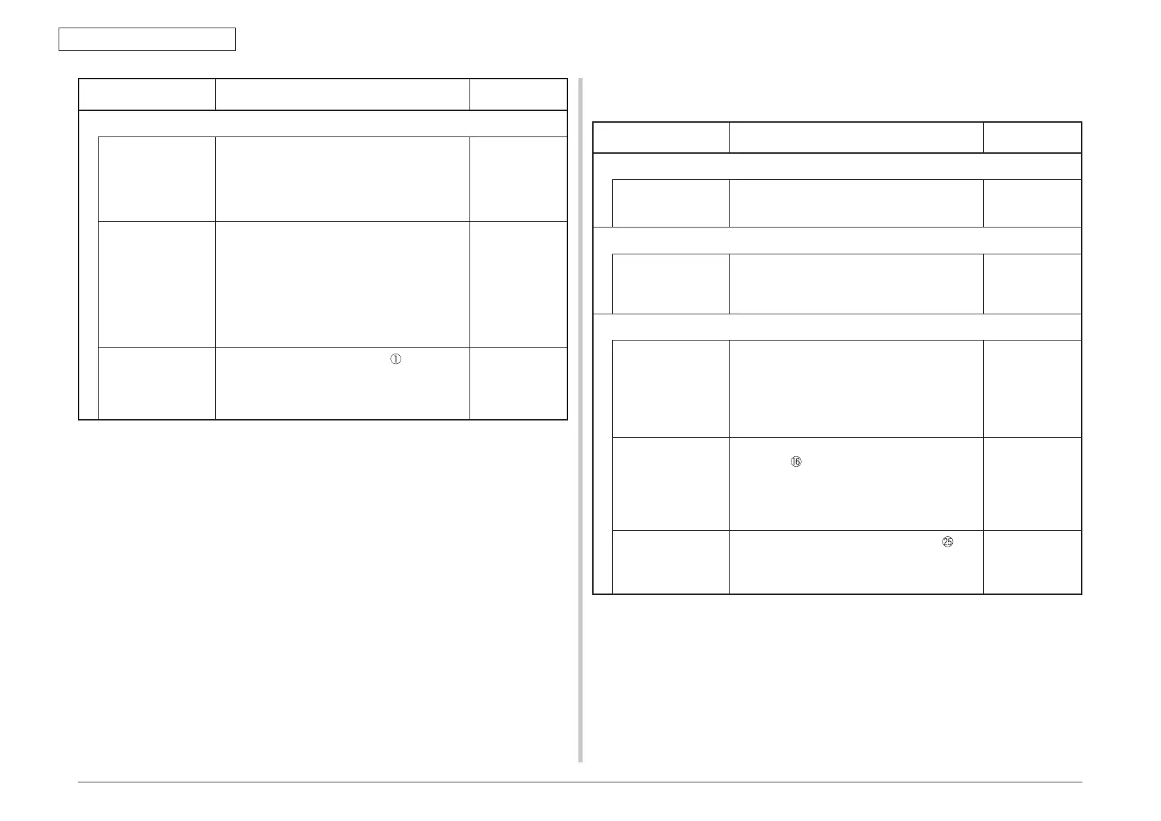
7.5.2.(5) Paper feed jam (error code 390: Multipurpose tray)
(5-1) Jam occurs immediately after the power is turned on. (Multipurpose tray)
Check item Check work
Action to be taken
at NG
(5-1-1) Check condition of the paper running path
P
aper running path
of the multipurpose
tr
ay
Check if paper is jammed or not in the paper
running path.
Remove the
jammed paper.
(5-1-2) Check condition of the mechanical parts
Chec
k the sensor
levers of the paper
entrance sensor 2
and the WR sensor.
Chec
k if shape and movement of the sensor
levers have any abnormality or not.
Replace the
sensor with the
good sensor
lever.
(5-1-3) Check condition of electrical parts
Check the detection
condition of the
sensor signal.
Confirm that the sensor signals are normally
detected by using the SWITCH SCAN function
of the self-diagnostic mode.
Replace either
the PU board
or the front
sensor board
(RSF PCB)
or connection
cable.
Chec
k the sensor
output signal level of
the paper entrance
sensor 2 and the
WR sensor
.
Check for the following signals at the FSNS
connector of the PU board.
Pin-2: WR sensor
Pin-3: Paper entrance sensor 2
Confirm that the above signal levels change
when the sensor lever is operated.
Replace the
front sensor
board (RSF
PCB)
Check the power
voltages supplied
to the front sensor
board (RSF PCB)
Chec
k the 5V power at the CN connector of
the front sensor board (RSF PCB).
Pin-1: 5V power supply
Pin-5:
0VL
Replace the
connection
cable.
Check item Check work
Action to be taken
at NG
(4-2-4) Check the system connection
Paper feed motor
drive cable
Check the connection condition of the cable.
Check if the connector is connected in the half-
way only or not, and check if the connector
is inserted in a slanted angle or not. Check
also that cables are assembled without any
abnormality.
Replace the
cable with the
good cable
that normalizes
the connection
condition.
Paper feed motor
drive cable
Check that any cable is not pinched during
assembling of the printer.
Remove the HOPSIZE connector no. 1 of the
PU board and check the followings at the cable
side.
Short circuit between pin-1 – FG
Short circuit between pin-2 – FG
Short circuit between pin-3 – FG
Short circuit between pin-4 – FG
Replace the
cable with the
good cable
that normalizes
the connection
condition.
Paper feed motor Remove the HOPSIZE connector
of the
PU board and check that approx. 3.4
Ω
can be
measured between pin-1 -pin-2 at the cable end,
and that approx. 5
Ω
can be measured between
pin-3 -pin-4 respectively.
Replace the
paper feed motor.