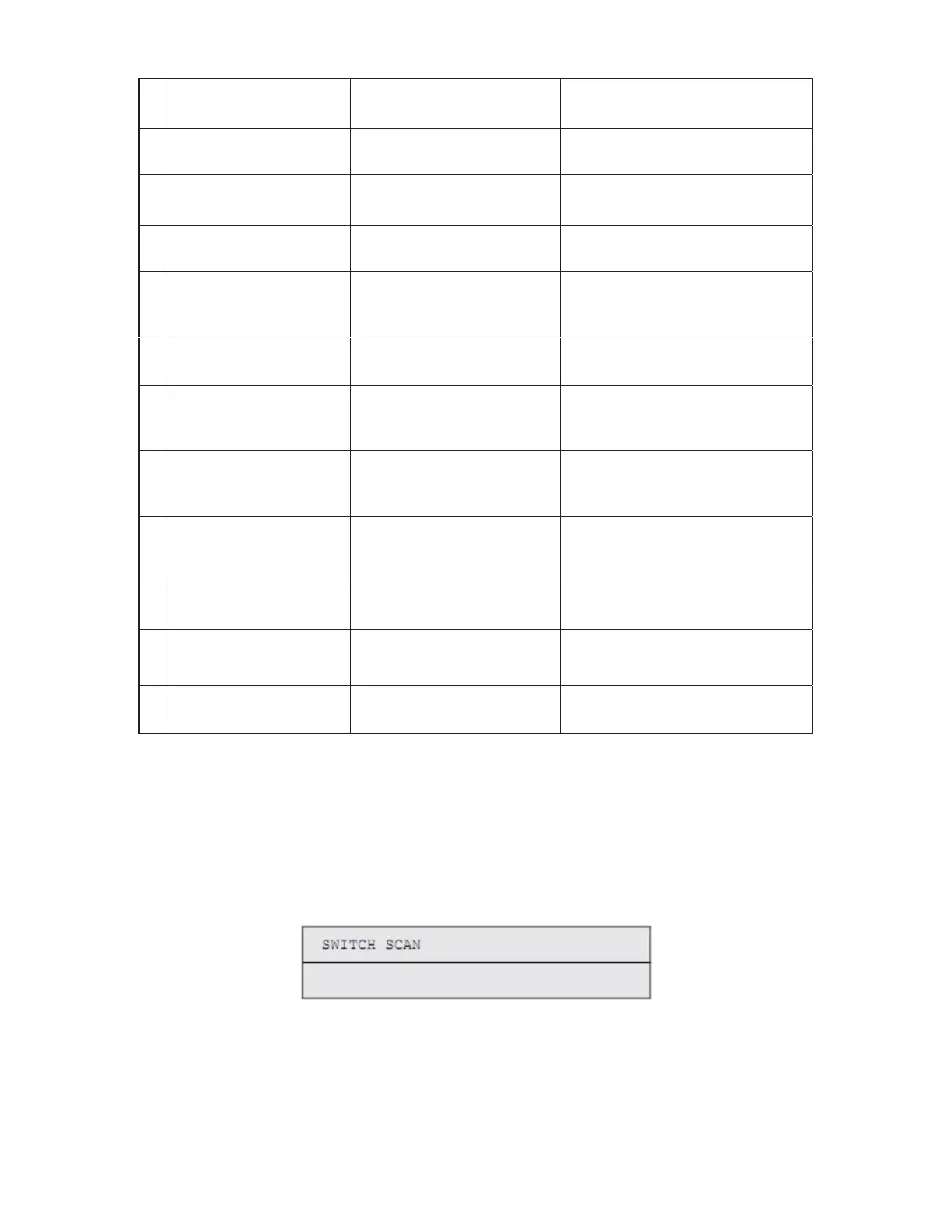
The following is the normal self-diagnostic mode menu:
Option Self Diagnostic Menu
Item
Adjustment
1 Switch scan test
(See section 2.8.1)
SWITCH SCAN Performs input sensor and switch
checking.
2 Motor and clutch test
(See section 2.8.2)
MOTOR&CLTCH TEST Tests motor and clutch
operation.
3 Test printing
(See section 2.8.3)
TEST PRINT Prints a test pattern stored in the PU.
4 Color registration
adjustment test
(See section 2.8.4)
REG ADJUST TEST Judges the color registration
adjustment mechanism as pass or fail.
5 Density adjustment test
(See section 2.8.5)
DENS ADJ TEST Judges the density adjustment
mechanism as pass or fail.
6 Consumable counter
display
(See section 2.8.6)
CONSUMABLE STATUS Displays consumable usage.
7 Consumable life counter
display
(See section 2.8.7)
PRINTER STATUS Displays consumable life.
8 Factory/Shipping mode
setting
(See section 2.8.8)
Switches between the Factory and
Shipping modes
9 Fuse status display
(See section 2.8.9)
FACTORY MODE SET
Displays the status of the fuses.
10 Engine parameter setting
(See section 2.8.10)
SENSOR SETTING
Sets whether to enable or disable
error detection performed by each
sensor.
11 NVRAM parameter setting
(See section 2.8.11)
NVRAM PARAMETER Must not be used.
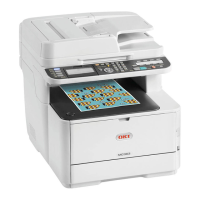
2.8.1 Switch Scan Test
The switch scan test is used for input sensor and switch checking.
1. Enter the self-diagnostic mode (level 1) and, until SWITCH SCAN appears on
the upper display, press [2] or [8] ([2] displays the next test option and [8]
displays the preceding test option). Then press the [6] button.
2. Press [2] or [8] until the option for unit(s) to test, which is shown in table below,
appears on the lower display ([2] displays the next option and [8] displays the
preceding option).
23