44473001TH Rev.1
114 /
Oki Data CONFIDENTIAL
4.REPLACEMENT OF PARTS
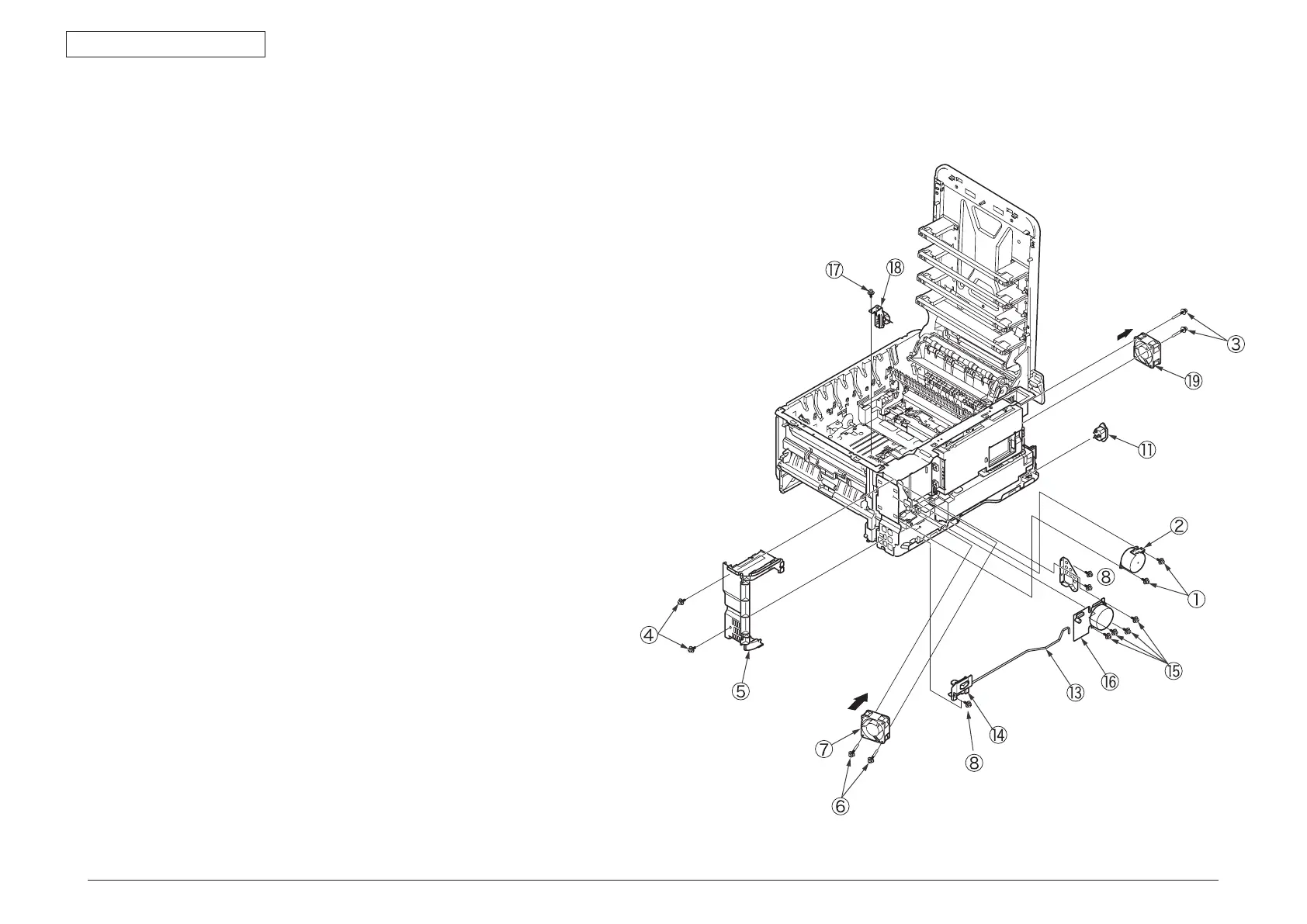
4.2.15 Front fan, hopping motor, rear fan, image drum
motor and cover-open switch
(1) Remove the left side cover, the right side cover, the rear cover, the MPT assembly,
the plate-rear, the plate shield assembly and the operator panel assembly.
(2) Remove the two (silver-colored) screws
①
to detach the hopping motor
②
.
(3
) Remove the two (silver-colored) screws
③
to detach the rear fan.
(4
) Remove the two (silver-colored) screws
④
and unlatch the frame-MPT-side
⑤
to
remove it.
(5
) Remove the two (silver-colored) screws
⑥
to detach the front fan
⑦
.
(6
) Remove the four (silver-colored) screws
⑧
and the (FG) screw
⑨
to remove the
plate support
⑩
, the AC inlet
⑪
, the shaft
⑬
and the switch
⑭
.
(7
) Remove the four (silver-colored) screws
⑮
to detach the image drum motor
⑯
.
(3
) Remove the screw to detach the cover-open switch.
Note!
• Observe the orientation to attach the low-voltage fan
⑥
.
• Be sure of the AC input voltage setting to attach the low-voltage power supply
③
.
10
0V : Attach a short plug to connector CN6.
230V : Attach no short plug to connector CN6.
• The low-voltage power supply
③
and the AC inlet assembly
⑤
. should
be replaced combined (they have been qualified to a safety standard,
combined).
• Th
e number of screws varies depending on the fusing motor:
Three : 43963301 (Sanyo)
Four : 43070601 (Nidec)
• While removing or installing FAN
⑦
,
⑲
, do not press impeller of the FAN
⑦
,
⑲
.
In case of the impeller unfastened by mistake, do not reuse it and install a
new FAN.